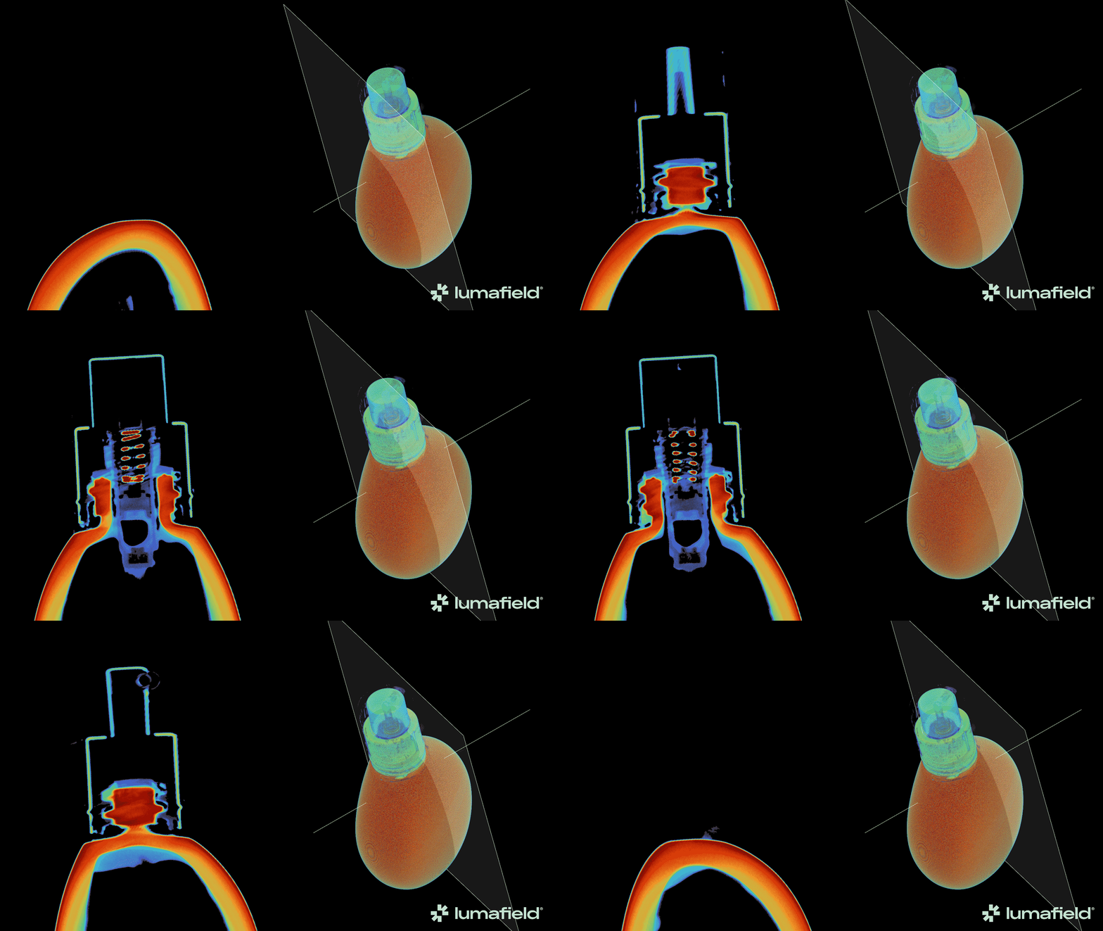
Creating a Custom Slice Plane
First, select a Reconstruction or ROI to serve as the parent Data Object for the Custom Slice Plane. Next, select the Slice Tool from the Toolbar.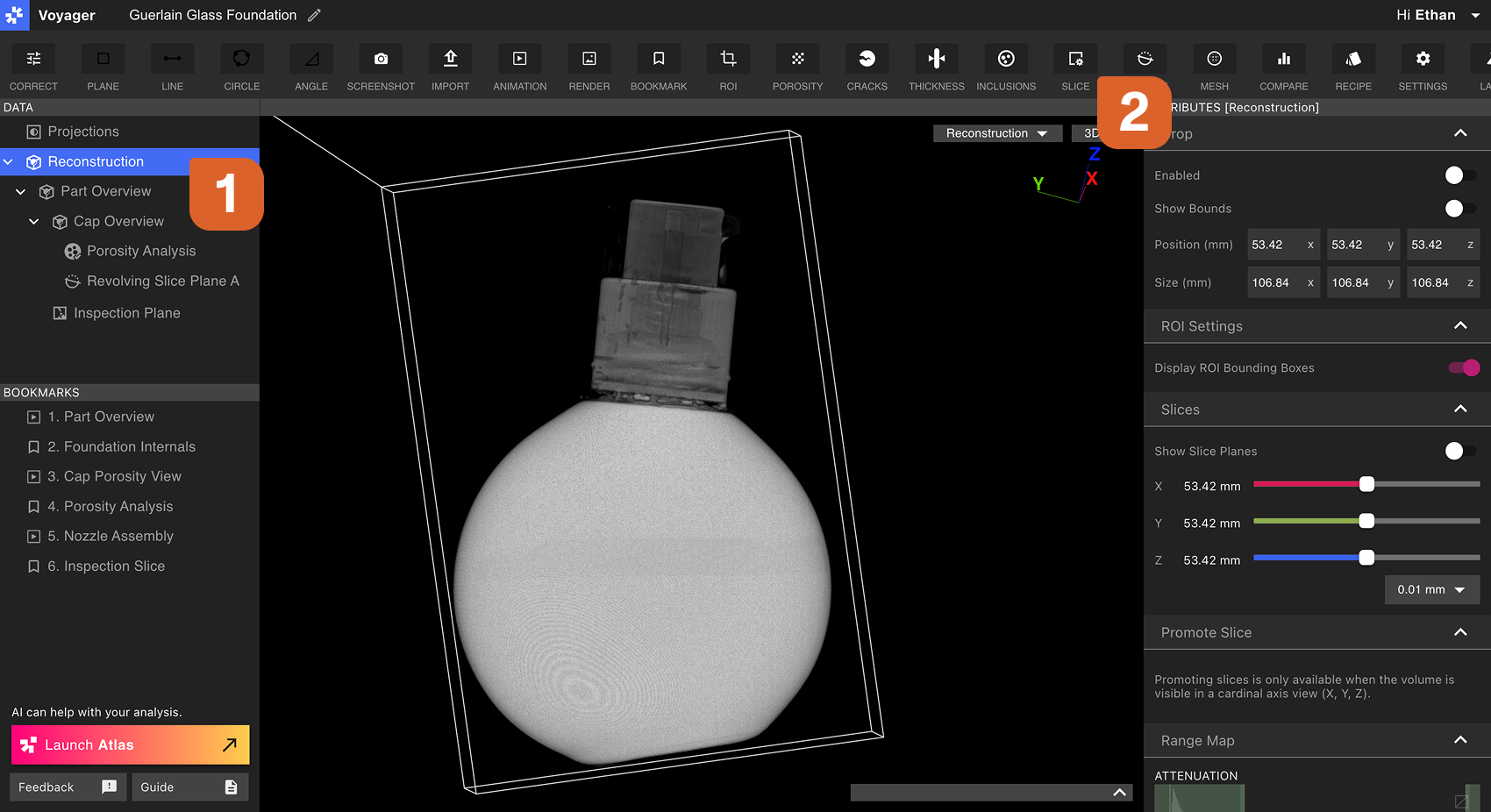 Use the Rotation Handles and Translation Handles in the Workflow Editor to orient and move the Custom Slice Plane to the desired position. Choose a length for the Axis, and scrub through the Custom Slice Plane using the Slice Depth Slider.
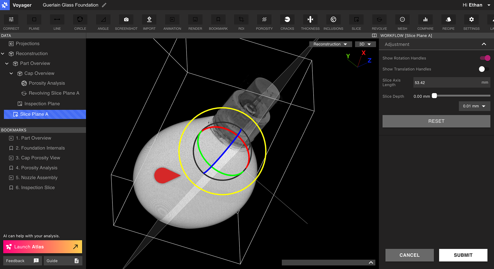
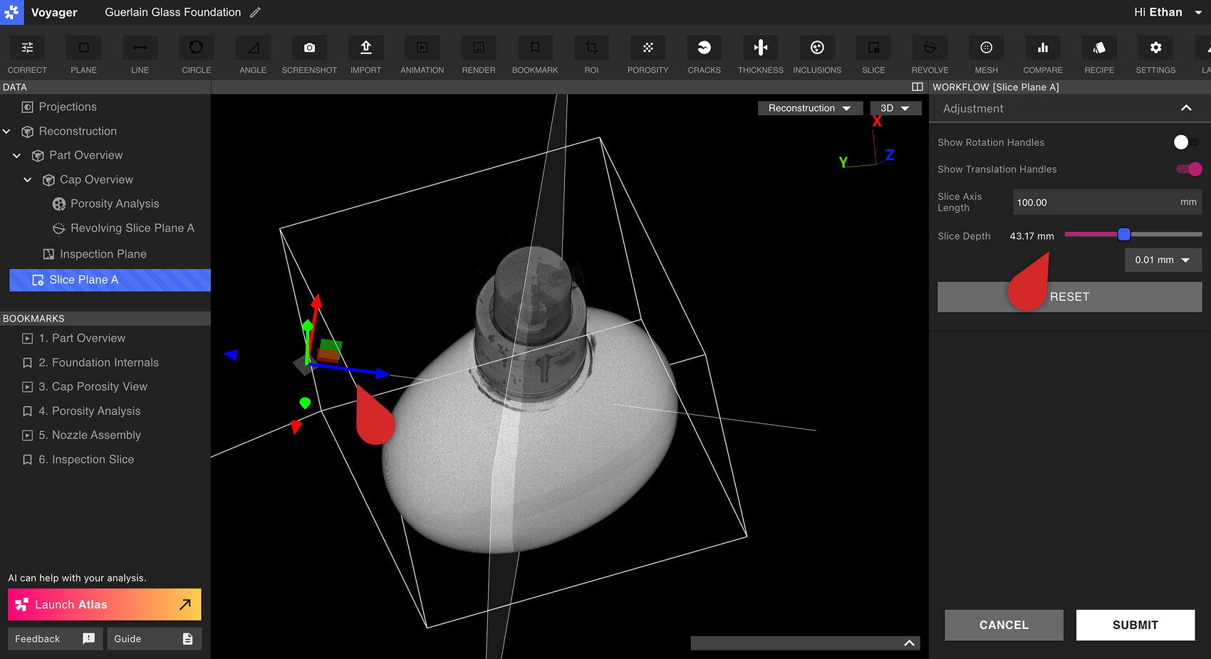 Select Submit to create the Custom Slice Plane. The new Custom Slice Plane Data Object will appear in the Data Panel immediately.
Viewing a Custom Slice Plane
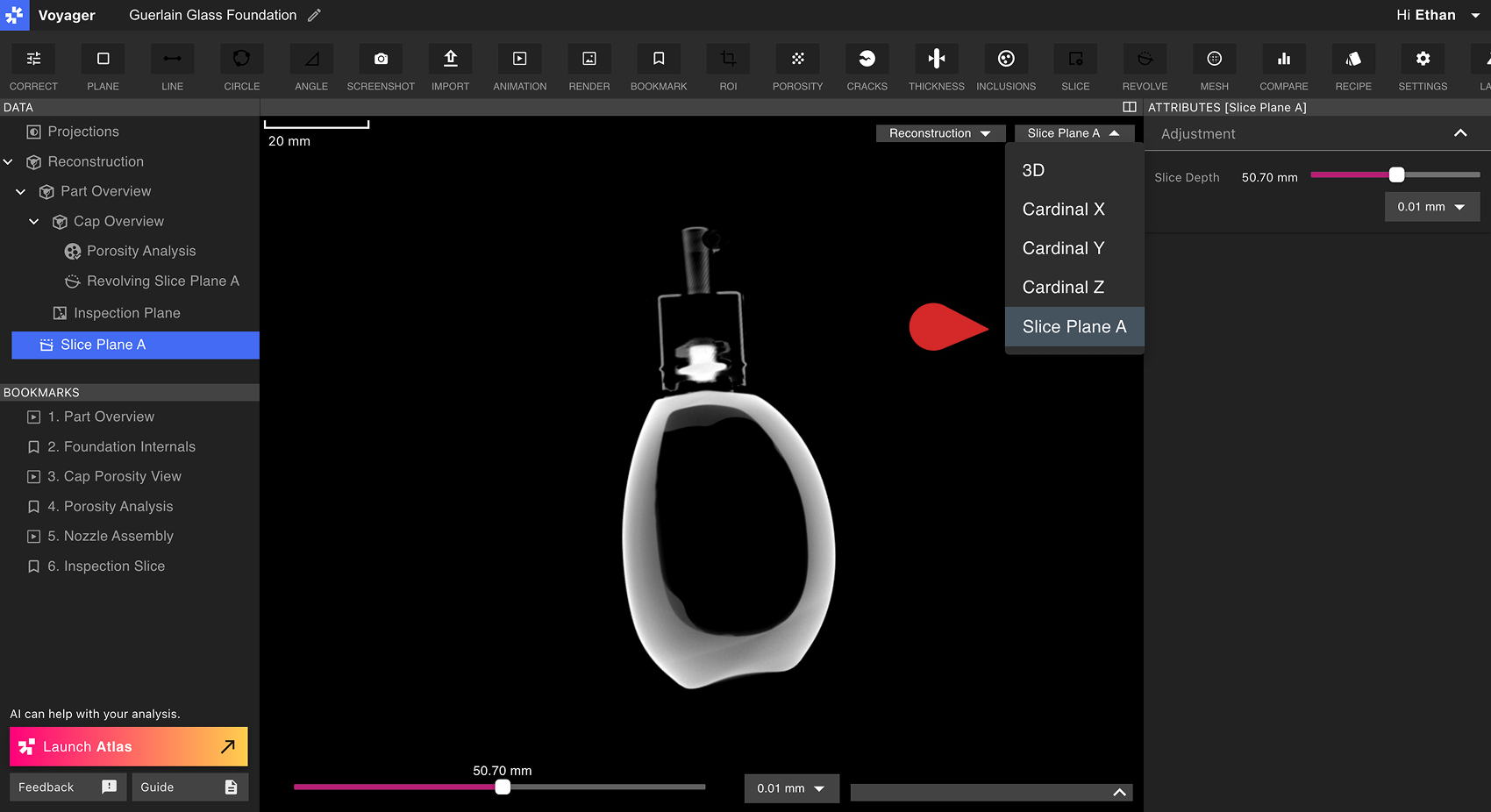
A Custom Slice Plane behaves like a Cardinal X, Y or Z plane of a Reconstruction or ROI. Selecting a Custom Slice Plane brings it into the Viewport, and a Slice Depth slider appears both at the bottom of the Viewport as well as in the Attributes Panel. Open a Custom Slice Plane from the Data Panel, or use the Go to control next to the custom plane slider in the Attributes Panel. Custom Slice Planes are not listed among the X, Y, Z, and 3D buttons in the Viewport header.