> ## Documentation Index
> Fetch the complete documentation index at: https://support.lumafield.com/llms.txt
> Use this file to discover all available pages before exploring further.
# Direct Dimensions
> Distance, Angle, and Diameter measurements on extracted features in Dimensioning Mode
Direct Dimensions are the foundational measurement Tools of [3D Auto-Dimensioning](/voyager/voyager-auto-dimensioning). Use them to measure between automatically extracted features (planes and cylinders) on a Voyager scan with sub-voxel precision. Every Direct Dimension supports tolerance definition with pass/fail color coding, and leader and label placement can be adjusted at any time after creation.
All measurements should be performed on an [ROI](/voyager/voyager-region-of-interest) that roughly orients your part to the correct orientation. Skipping this step is the most common cause of poorly-oriented measurements.
The Direct Dimensions Tools are available in [Dimensioning Mode](/voyager/voyager-modes#dimensioning-mode) once Automatic Feature Extraction has run on the parent reconstruction. Every ROI built on that reconstruction inherits the extracted features, so a single extraction surfaces planes and cylinders across all child ROIs.
Distance
The Distance Tool measures between two extracted features. The supported feature pairs and methods today are:
* **Plane to Plane** — Center to Center, Max Perpendicular, Min Perpendicular, Min
* **Plane to Cylinder** — Center to Center, Centroid
* **Cylinder to Cylinder** — Center to Center, Centroid
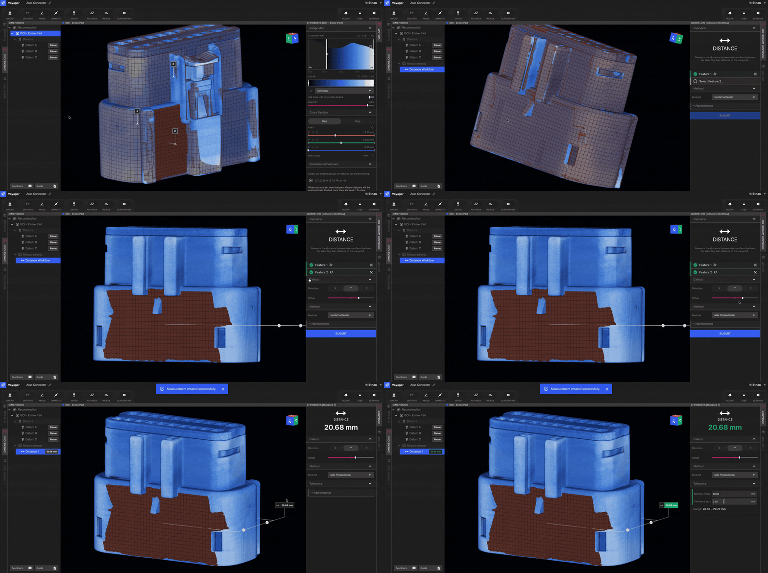
Workflow
Choose **Distance** from the Toolbar in Dimensioning Mode.
Click the first extracted feature in the Viewport, then click the second. Eligible features highlight on hover so you know which surfaces are available.
Pick a method from the dropdown in the Workflow Editor (the available methods depend on the feature pair you selected) and enter a tolerance.
Submit to compute the dimension. The result is added to the scene with a leader line and a tolerance-aware color code.
The supported method matrix is actively being extended. Reach out to Lumafield to share dimensional requirements that aren't yet covered.
Angle
The Angle Tool measures the angle between two features. Supported pairs:
* **Plane to Plane**
* **Plane to Cylinder**
* **Cylinder to Cylinder**
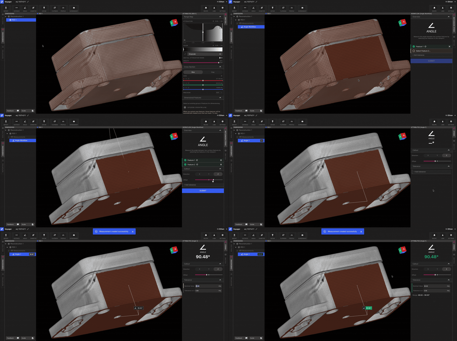
Workflow
Choose **Angle** from the Toolbar.
Select the two extracted features whose included angle you want to evaluate.
Enter the tolerance and submit. The angle and pass/fail state appear in the dimension label.
Diameter
The Diameter Tool measures the diameter of any extracted cylinder. This is the simplest of the Direct Dimensions Tools — point and select.
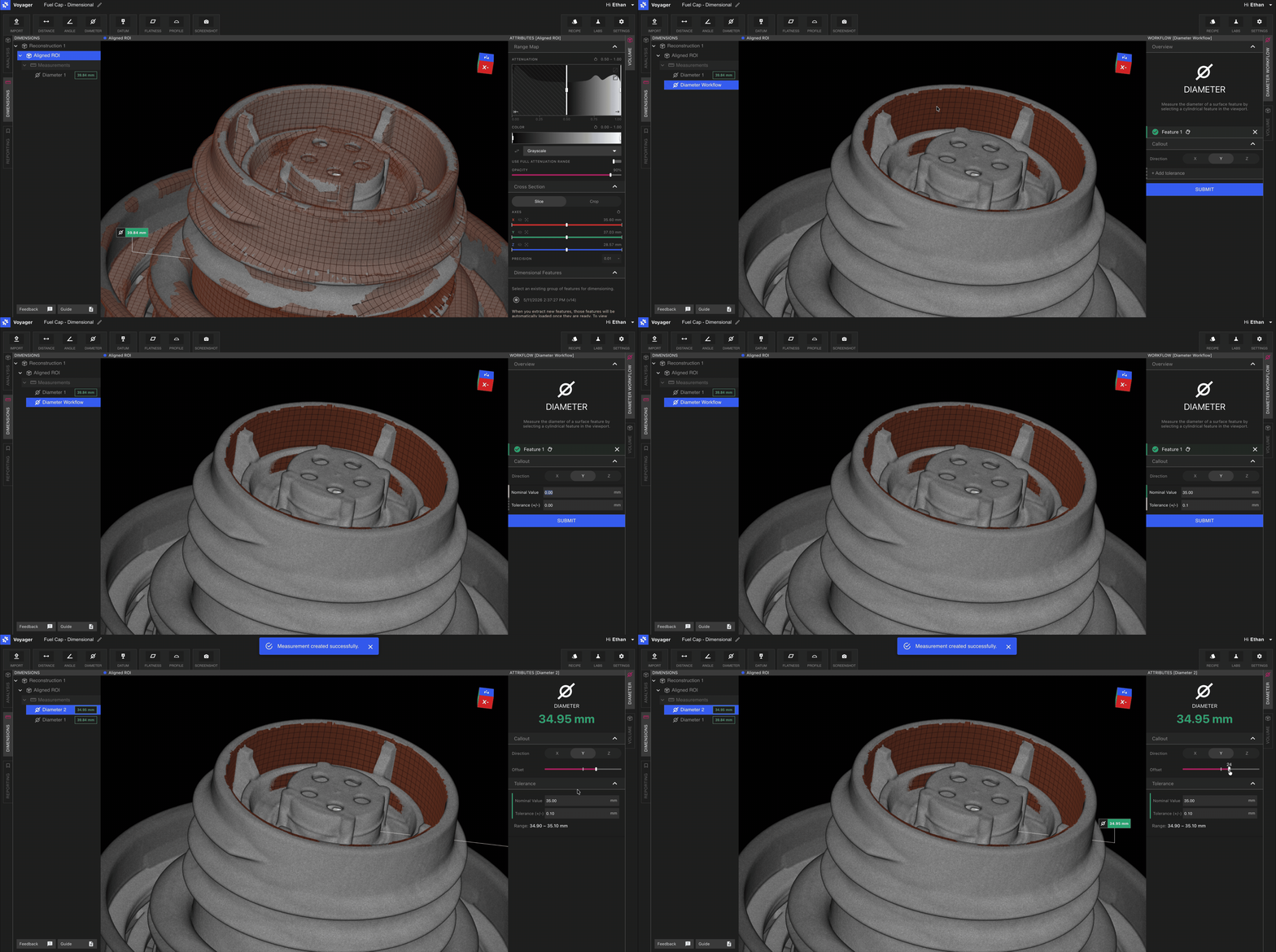
Workflow
Choose **Diameter** from the Toolbar.
Click an extracted cylindrical feature.
Enter the tolerance and submit.
Tolerance and pass/fail color coding
Every Direct Dimension supports tolerance definition. When a tolerance is set:
* The dimension label is **green** when the measurement is within tolerance.
* The dimension label is **red** when the measurement is out of tolerance.
Tolerance values can be modified after the measurement is completed — open the dimension in the Attributes Panel to update the value or method, and the color coding updates immediately. This makes it easy to iterate on tolerances without re-running the workflow.
Adjusting leaders and labels
Once a Direct Dimension is created, use the leader and label controls in the Attributes Panel to adjust orientation and offset. This keeps complex scenes with many dimensions easy to read and helps when preparing Bookmarks, Renders, and Animations in [Reporting Mode](/voyager/voyager-modes#reporting-mode).
Related pages
* [3D Auto-Dimensioning](/voyager/voyager-auto-dimensioning) — feature extraction and Mode setup
* [Flatness](/voyager/voyager-flatness)
* [Datum Definition](/voyager/voyager-datums)
* [Profile](/voyager/voyager-profile)
* [Voyager Modes](/voyager/voyager-modes)
* [Voyager 2.0 Release Notes](/platform/voyager-release-notes) and [Monthly Highlights](/platform/monthly-highlights)