Use the same steps to create Inspection Planes and take dimensions across Cardinal, Custom, and Revolving Slice Planes.
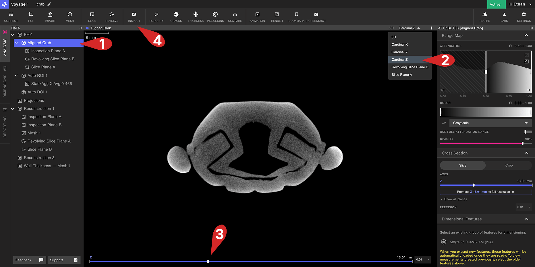
Creating an Inspection Plane
- Select a Data Object (Reconstruction, ROI, Revolving / Custom Slice Plane, Mesh, or Mesh Compare) to dimension.
- Select any 2D view in the Viewport panel, or if using split-views, the left panel of the Viewport. This can be a Cardinal 2D slice axes, a Revolving Slice Plane, or Custom Slice Plane. A Revolving or Custom Slice Plane can also be selected directly from the Data Panel.
- Select a slice to produce an Inspection Plane of by dragging the slider at the bottom of the Viewport to the desired position, or by using the slider in the Attributes Panel.
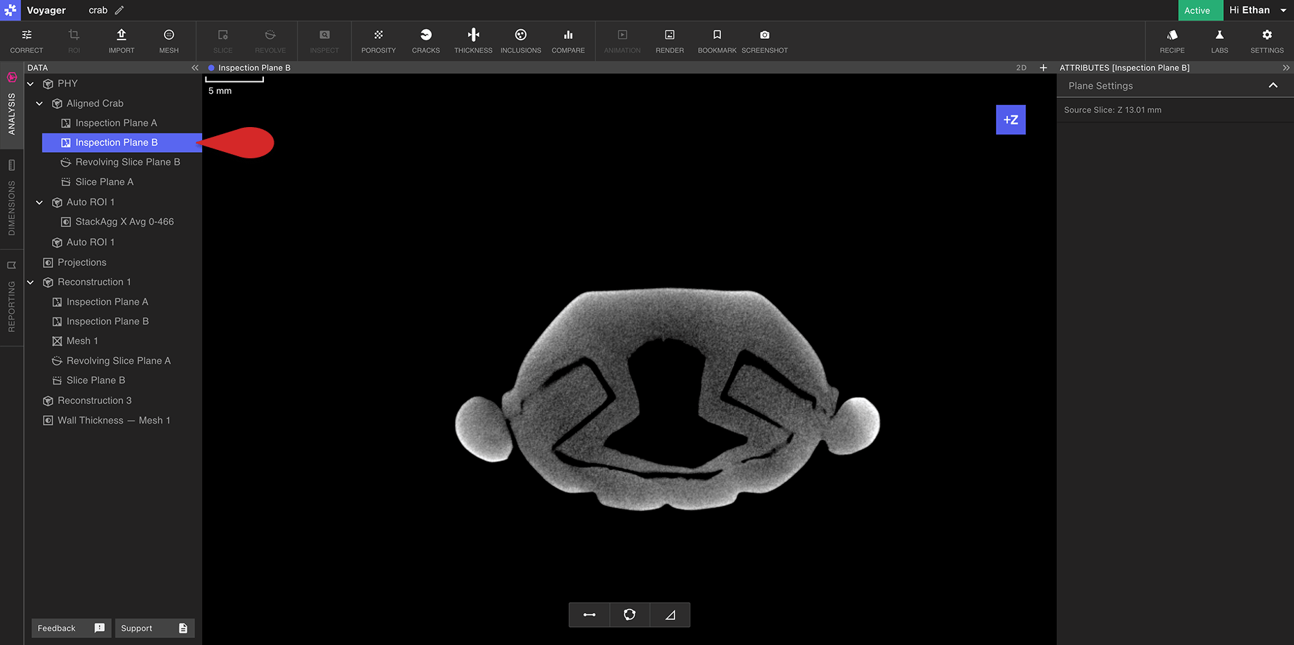
- Select the Plane Tool to lock in the current plane for inspection and to generate a new Inspection Plane Data Object