ISO-50 Method and Part Selection
The ISO-50 method of boundary selection is accurate for scans of low attenuation mono-material parts. Some examples include injection molded single-plastic parts, 3D printed single material parts, and parts made of fiberglass or other relatively low attenuation material. The method works by identifying the two primary attenuation values in the volume (in an ideal part, these voxels are clustered around the part material and the air in the scan), and then finding the exact 50% midpoint between them. That midpoint is a statistically accurate part boundary. By generating a Mesh from the volume at that threshold, you are extracting an accurate part boundary with which to perform subsequent analyses such as dimensioning and surface comparison.Workflow
Step 1: Identify an appropriate scan and create an oriented ROI of the portion of the scan you wish to dimension or compare.
Use the ROI Tool to create the smallest, cardinally oriented ROI of the features you wish to dimension.
Step 2: Use ISO-50 to generate an accurate boundary Mesh of that part.
Select the ROI that you created in Step 1 and click the Mesh button in the Toolbar. Instead of choosing a threshold manually, turn on the ISO-50 toggle. Select a factor of Mesh smoothing if your scan is somewhat noisy. A small amount of Mesh smoothing can have a beneficial impact with very little impact on accuracy. Note that a large amount of Mesh smoothing (greater than 1) can introduce negative errors on positive corners and positive errors on inside corners. Request a Mesh with the Create Mesh button. If the returned Mesh has a noisy surface that is not present in the physical part, consider increasing the Mesh smoothing. Detail of ISO-50 Toggle in Mesh workflow: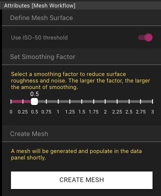
Step 3: Slice into the Mesh to the features you wish to dimension and establish your inspection planes.
Select the Mesh you created in the Data Panel. Use the Viewport selector to choose an axis that you wish to slice to, and slice to the location of the features you care about. Click Inspection Plane in the Toolbar to establish an inspection Plane.Step 4: Use the Mesh-snapping features to remove human click-error and dimension your features accurately.
Now choose the line, circle or angle dimensioning Tool. When you hover over the Viewport you can see there is a yellow dot that glides along the surface of the Mesh.