> ## Documentation Index
> Fetch the complete documentation index at: https://support.lumafield.com/llms.txt
> Use this file to discover all available pages before exploring further.
# Nominal CAD Import
> Upload a .STEP file as the nominal CAD reference for Profile evaluation
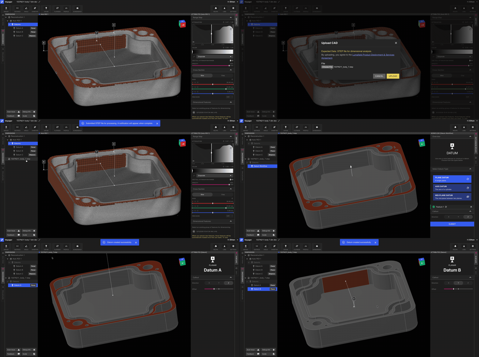
In [Dimensioning Mode](/voyager/voyager-modes#dimensioning-mode), the [Import Tool](/voyager/voyager-import) loads a `.STEP` file as the **nominal CAD body** for your scanned part. The imported CAD is the reference geometry that [Profile](/voyager/voyager-profile) evaluates the scan against, and is also where you define the CAD-side half of your Datum Reference Frame using the [Datum Tool](/voyager/voyager-datums).
This page covers the Dimensioning Mode workflow for nominal CAD import. For the broader Import Tool — including `.STL` Mesh import in [Analysis Mode](/voyager/voyager-modes#analysis-mode) — see the main [Import Tool](/voyager/voyager-import) article.
Why a separate workflow
Nominal CAD import is the only point in [3D Auto-Dimensioning](/voyager/voyager-auto-dimensioning) where data enters Voyager from outside the scanner. The CAD body provides:
* The **exact nominal geometry** that Profile compares against your scan.
* A surface on which you can build a CAD-side **Datum Reference Frame** that mirrors the DRF defined on the scanned part.
Because STEP carries native units and exact geometry, no scale entry is required at import time — Voyager preserves the units defined in the file.
Workflow
Select the **Dimensioning** tab from the Mode tabs on the left-hand side of Voyager.
Select the Import Tool from the Toolbar. In Dimensioning Mode the Import Tool accepts `.STEP` files.
Choose the STEP file representing the nominal part. The imported body appears in the Data Panel as a new Data Object.
Use the [Datum Tool](/voyager/voyager-datums) to build a DRF on the imported CAD that mirrors the DRF on the scanned part. Matching labels (for example, `A`, `B`, `C`) make datum correlation in Profile trivial.
With matching DRFs on both the part and the CAD, run [Profile](/voyager/voyager-profile) to evaluate deviation.
Export STEP files from your CAD tool with the part isolated as a single body. Multi-body assemblies should be split before upload so Profile evaluates the intended geometry.
File guidance
A few practical tips for clean STEP imports:
* **Single body per file.** If your CAD model contains assemblies or fixtures, export only the part to be evaluated.
* **Native units preserved.** STEP files declare their own units; Voyager respects them. There is no scale field to set, unlike the `.STL` flow in Analysis Mode.
* **Geometry, not tessellation.** STEP is exact geometry, so polygon count is not a concern — unlike the `.STL` flow used by the [Compare Tool](/voyager/voyager-cad-comparison), where polygon density affects accuracy.
Related pages
* [Import Tool](/voyager/voyager-import) — main article covering both `.STL` and `.STEP` workflows
* [Voyager Modes](/voyager/voyager-modes)
* [3D Auto-Dimensioning](/voyager/voyager-auto-dimensioning)
* [Datum Definition](/voyager/voyager-datums)
* [Profile](/voyager/voyager-profile)
* [Voyager 2.0 Release Notes](/platform/voyager-release-notes) and [Monthly Highlights](/platform/monthly-highlights)