Skip to main contentWhen working with a part that exhibits a cylindrical or spherical geometry, use a Revolving Slice Plane to rotate 360° around a custom-defined axis.
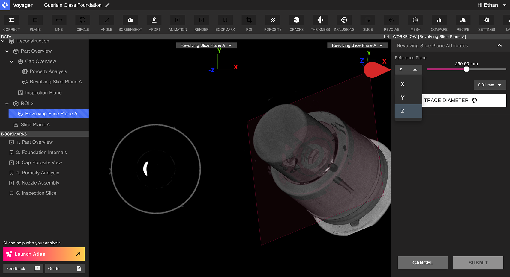
Creating a Revolving Slice Plane
First, select a Reconstruction or ROI Data Object from the Data Panel. To create a useful Revolving Slice Plane, be sure that the desired axis of rotation is aligned to either the Cardinal X, Y, or Z axis of the Data Object. If none of these axes match, create an ROI with the desired axis of rotation aligned to a Cardinal plane.
From the dropdown menu in the Workflow Editor, select the Cardinal X, Y, or Z Plane to use as the Reference Plane. Select a location along the Plane that exhibits a circular geometry to easily capture the desired axis of rotation.
Select Trace Diameter from the Workflow Editor. Select three points on a circular geometry of the part. The midpoint of this circle will define the axis of rotation around which the Revolving Slice Plane will revolve.
View the Revolving Slice Plane before submitting it using the Slice Angle slider in the Workflow Editor. By default, the Viewport will be split 2D and 3D views to best preview the current Revolving Slice Plane. Select Redraw to reselect a circle, or select Submit if satisfied.
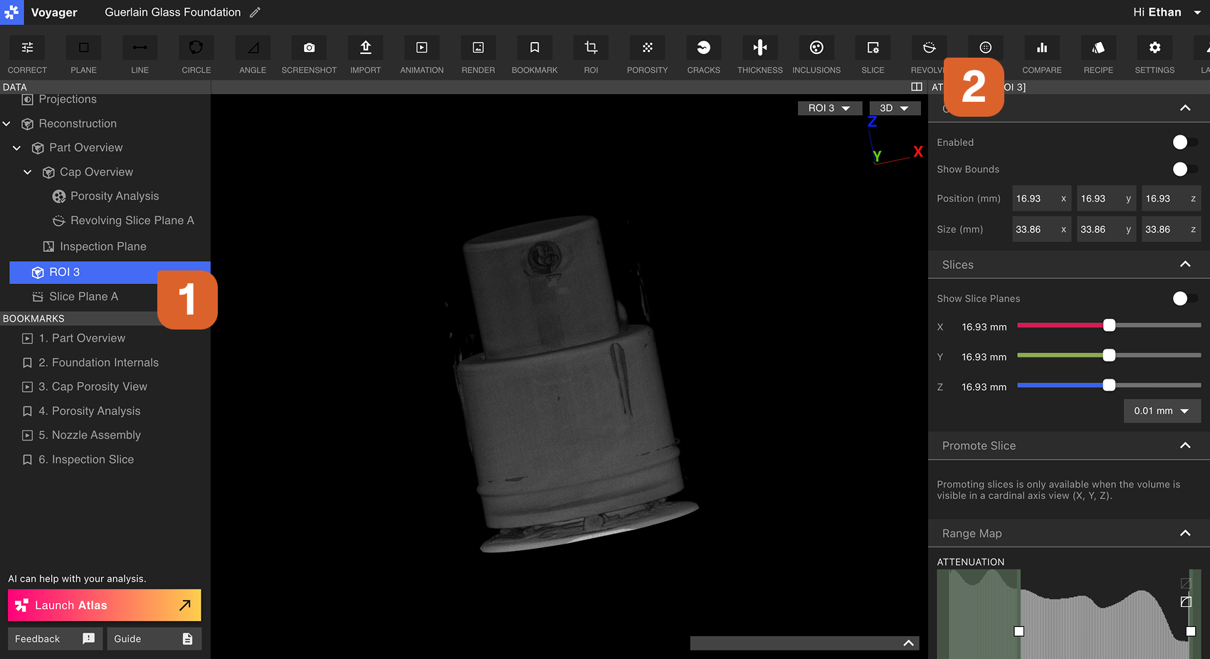
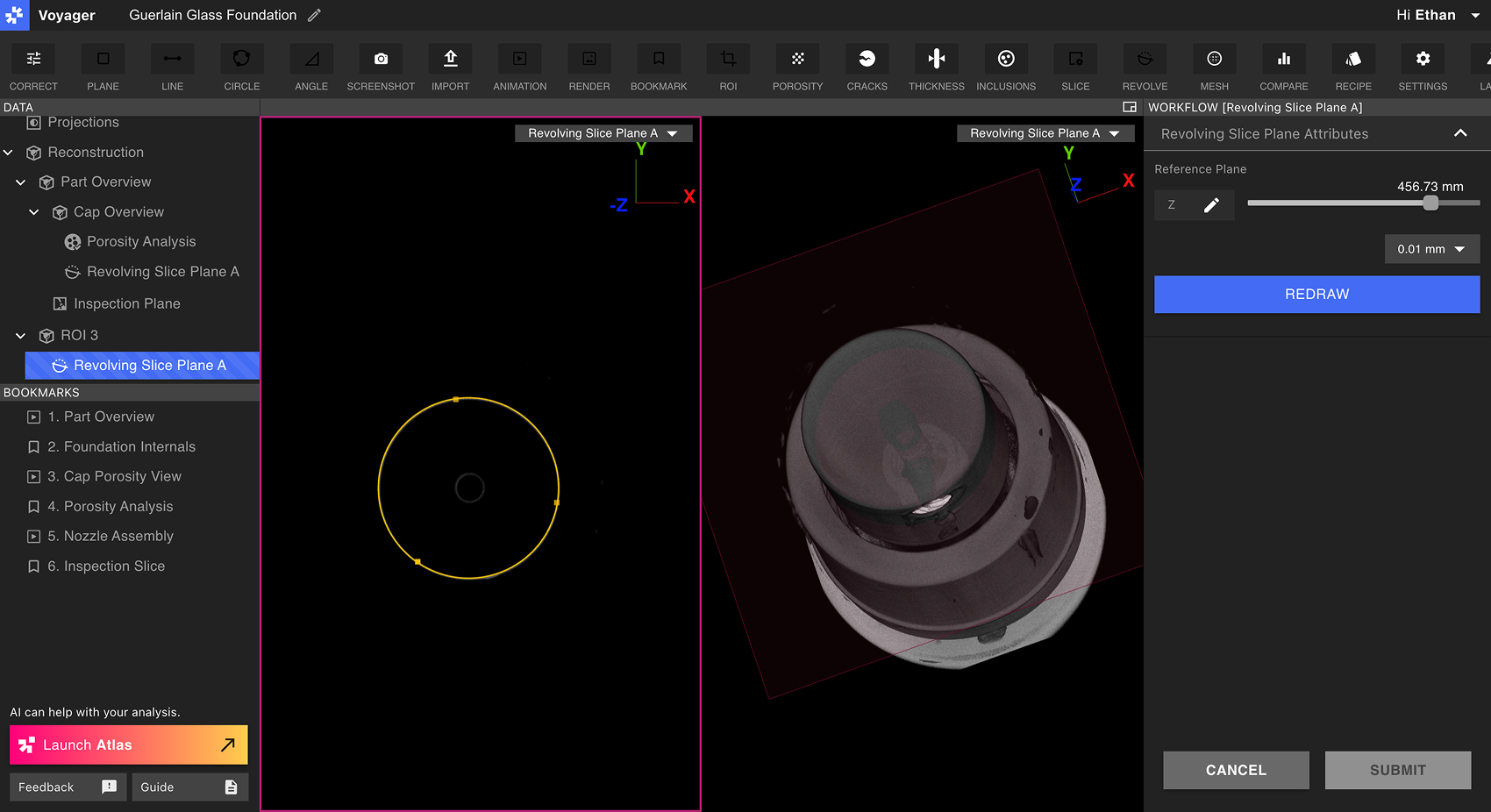
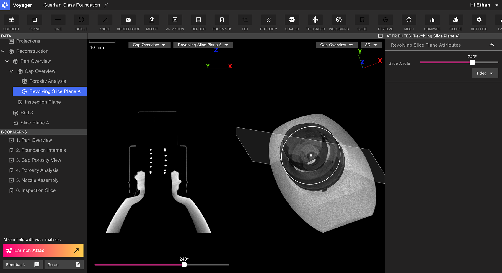
Viewing a Revolving Slice Plane
Select a Revolving Slice Plane from the Data Panel to bring it into the Viewport. Revolving Slice Plane Data Objects can also be selected from the View dropdown at the top-right of the Viewport when their parent Data Object is selected.
When a Revolving Slice Plane is selected, the Slice Angle slider appears both in the bottom of the Viewport as well as in the Attributes Panel. Slide the Slice Angle control to view data in 360° around the Revolving Slice Plane.