Positioning fundamentals and safety
Effective part positioning is a balance of two primary objectives:- Hardware safety: Preventing collision between your part and the scanner components
- Optimizing resolution: Ensuring scan quality and resolvability for your specific object or area of interest
Manual verification
The Neptune system does not utilize proximity sensors to automatically prevent hardware collisions. Therefore, the operator is responsible for ensuring clear paths of motion.Emergency procedures
If you observe an imminent collision or any unexpected movement during positioning:- Emergency Stop: Press the red Emergency Stop (E-Stop) button to halt all gantry and stage motion. Only resume movement once you have verified that the part has a safe path of travel
- Rehoming: Following an E-Stop trigger or a physical hardware collision, you must rehome the system. This process recalibrates all motion axes, ensuring the system’s positional accuracy is restored before you resume operation
- Contact support: If a crash has occurred or if you encounter any abnormal scanner behavior, email support@lumafield.com immediately to confirm the condition of your machine. Include photos/videos of the current state and a description of the event to help Lumafield’s Engineering Team verify the system’s integrity before resuming operation
Adjust position and magnification
Use the touchscreen sliders, arrow keys, or manual value entry to define your scanning position. Precise alignment is the first step toward ensuring both high-fidelity data and hardware safety.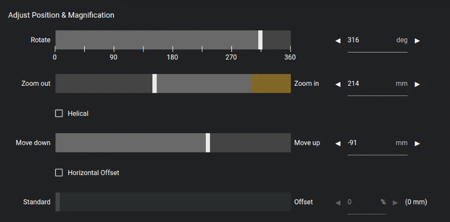
Positioning controls
Rotate: Perform a full rotation to verify that your part and any mounting fixtures maintain adequate clearance from the X-ray source, filter wheel, and detector.- Verify bounds: Use “Verify Bounds” for a quick automated clearance check and to ensure that your area of interest remains within the Field of View (FOV)
Note: If you are performing a Horizontal Offset Scan, Verify Bounds will only be used as a clearance check.
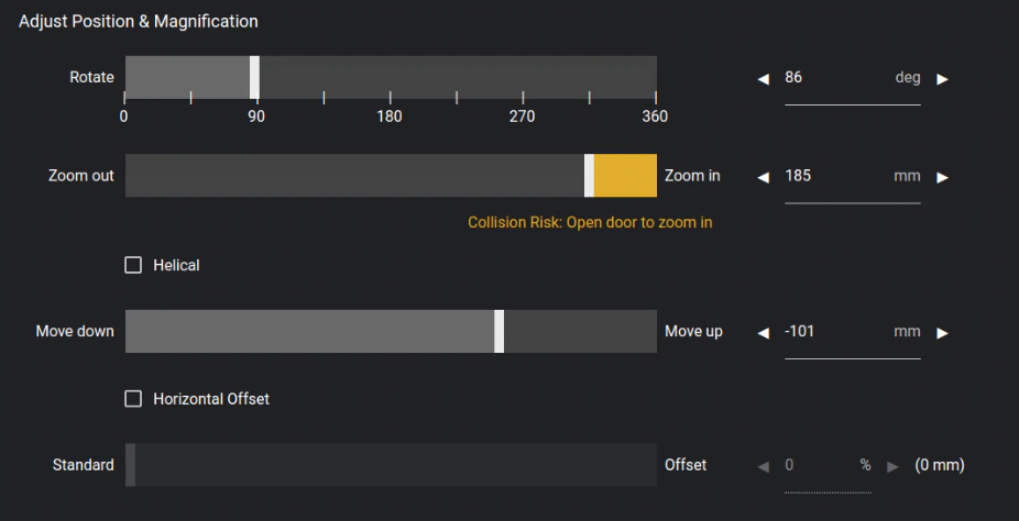
- The yellow zone: This highlighted area indicates high magnification and proximity to the source. When operating in this region, exercise extreme caution
- Filter wheel clearance: Always ensure there is sufficient physical space for the filter wheel to engage and rotate without striking your part or fixture
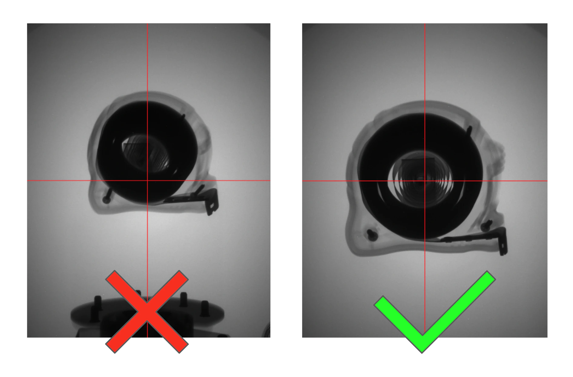
- Optimal exposure: The center of the FOV receives the highest X-ray flux (intensity). For the best scan quality, vertically center your part or areas of interest
- Artifact prevention: Ensure the turntable or motion stage is not visible in the FOV, as including high-density mounting hardware can introduce unwanted artifacts
Preferred magnification by model
Due to differences in hardware, follow these guidelines for optimal resolution:- Neptune Standard & Neptune MFX: Position the part as close to the source as safely possible. On these models, maximum proximity yields the highest resolution
- Neptune High Power: The ideal magnification is ~2x or positioning the part roughly halfway between the source and the detector. Pushing magnification higher on this model can lead to “blurring” due to the larger focal spot size at higher power levels
Advanced scanning modules
Depending on your scanner configuration, you may have access to specialized acquisition modes. These scanner modules leverage advanced reconstruction algorithms to transcend the physical limits of a standard scan volume:- Horizontal Offset Scan (Expanded Scan Volume Module): Use this mode to effectively double your scanning width, expanding the usable volume to nearly twice the standard envelope. By shifting the rotation axis and allowing the object to intentionally exit the Field of View (FOV) on one side, the software uses advanced mathematical reconstruction to “stitch” the offset data into a single, oversized volume.
- Helical Scan (Helical Scanning Module): Use this mode to extend the vertical scanning height beyond the limits of the standard scan volume. By synchronizing continuous vertical stage movement with rotation, the system provides uniform resolution across the entire length of the part and significantly minimizes cone-beam artifacts on horizontal surfaces.
Oversized parts and Flat Field Correction (FFC)
Flat Field Correction (FFC) images are reference frames captured by the detector of an unobstructed X-ray beam. These images establish a baseline for the detector’s sensitivity and the X-ray beam’s intensity, ensuring a high-quality, artifact-free reconstruction.- Initialization and caching: FFC images are captured during the scanning process and are cached for 3 days. If a new scan is run with the same settings, the FFC step is skipped and the cached images are used. New FFC images will be taken after the cache expires
- The “clear path” requirement: To capture a valid FFC, the X-ray’s path to the detector must be completely unobstructed. Depending on the scan settings, you may be prompted to remove your part so the system can calibrate. The system will otherwise move your part out of the way to an FFC position to take these images
- The risk of obstruction: If any part of your object (or fixtures) remains in the beam path during FFC image capture, the system will treat that object as a “permanent shadow.” This will result in artifacts appearing throughout your final scan data
Note: Should you suspect that an improperly captured FFC is affecting your scan quality, please reach out to support@lumafield.com for assistance.
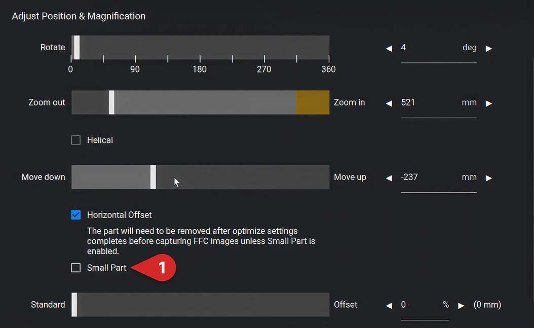
“Small Part” checkbox for Horizontal Offset Scans
When performing a Horizontal Offset Scan, the system will prompt for manual part removal before every scan to ensure a clear path for new FFC images. If your part is physically small enough that the system can achieve an unobstructed view of the detector by moving the stage to the internal FFC position, you can select the “Small Part” checkbox to streamline your workflow and bypass the need to manually remove your part.