Accessing the Data Quality Toolkit
Select the Labs Tool from the Toolbar, then open the Data Quality Toolkit App.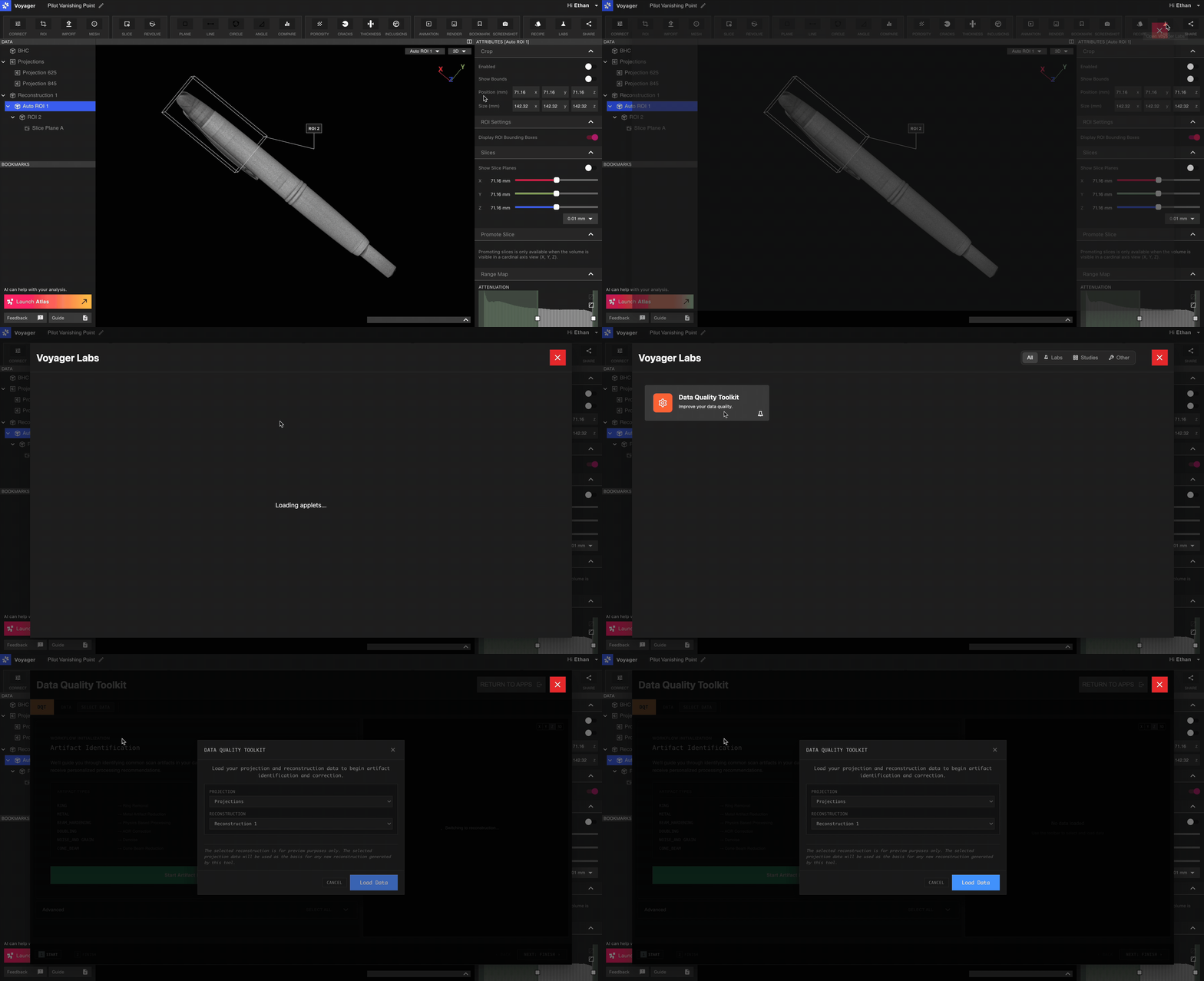
Produce a corrected Reconstruction
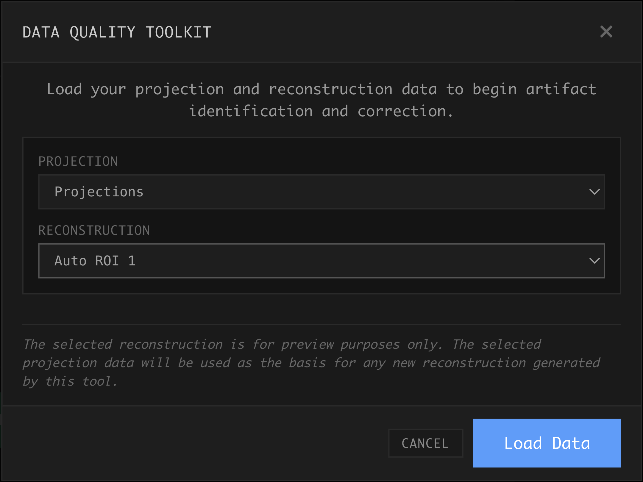
To begin using the Data Quality Toolkit, select the radiographs that your newReconstruction will be based on. For most Projects, this is an object called Projections. Select a preview Reconstruction or ROI. A Reconstruction or ROI in which the part is most easily visible is the best choice, as this will serve as the object from which artifacts will be identified. Choosing an aligned ROI may help with 2D visualization. Select Load Data to continue.
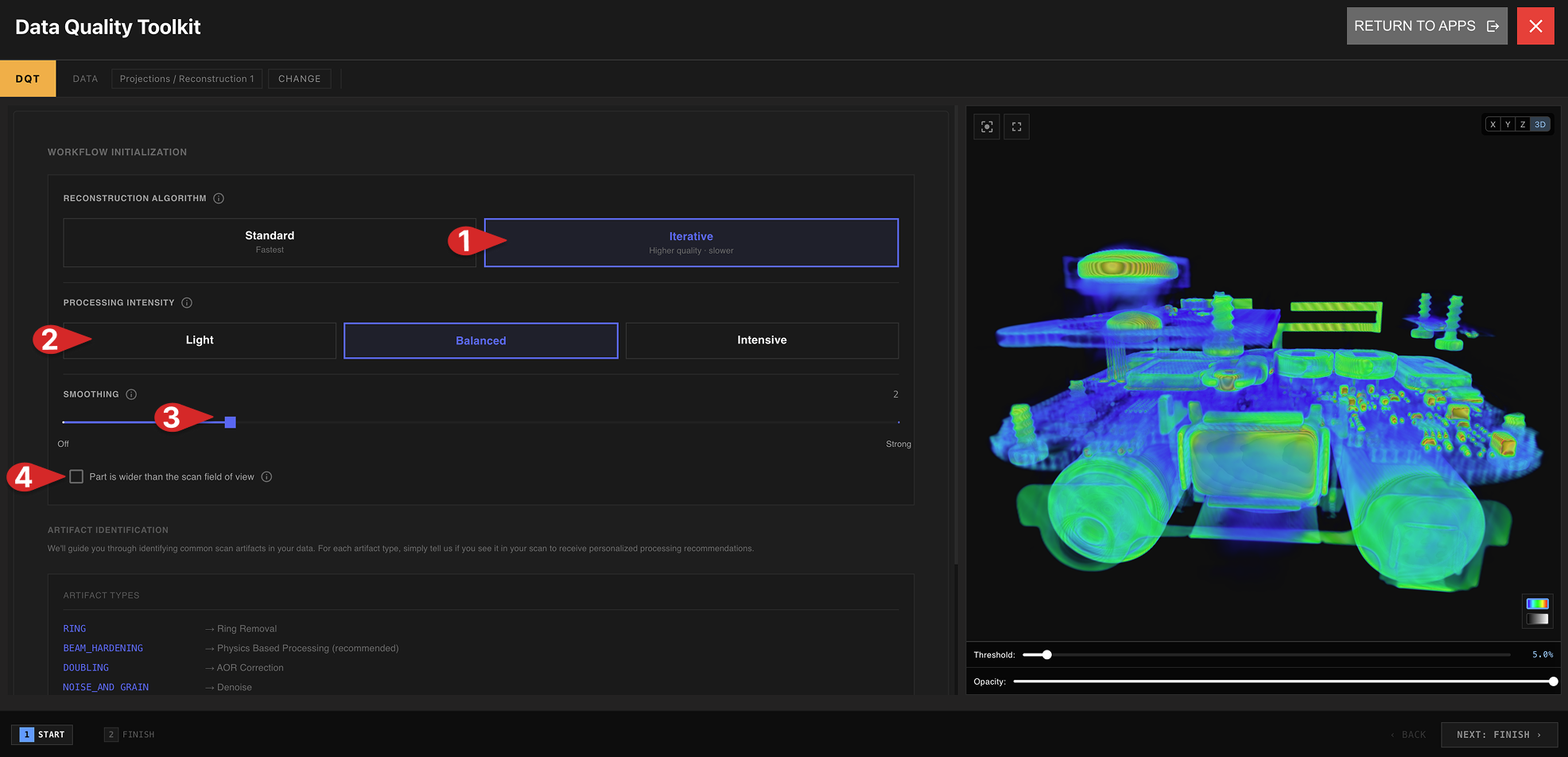
Choose a Reconstruction Algorithm
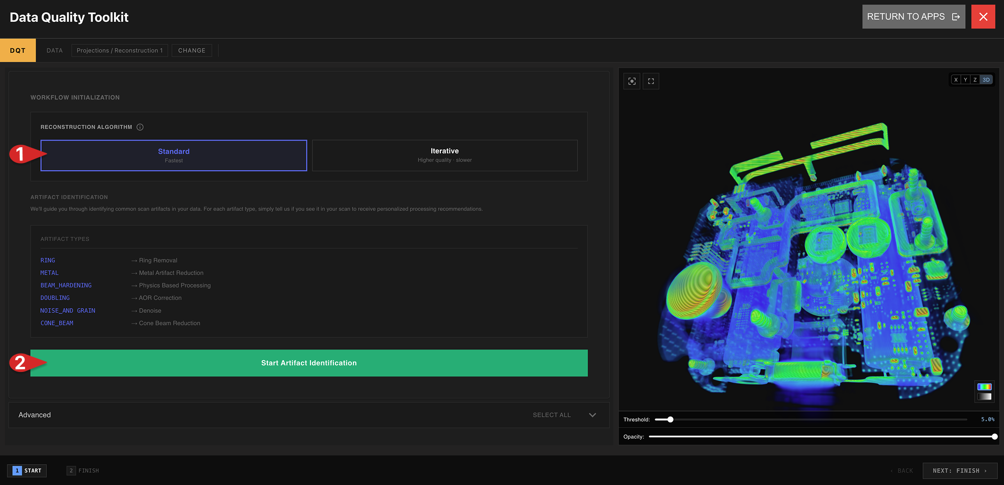
- Standard: Run Lumafield’s default Reconstruction algorithm, with data correction techniques applied to eliminate artifacts.
- Iterative: An intensive, higher-power Reconstruction algorithm. Iterative Reconstructions take longer to process than Standard Reconstructions.
For Iterative Reconstructions, applying Physics-Based Processing is recommended for best results. Iterative Reconstruction and Physics-Based Radiograph Processing now return corrected reconstructions sooner.
- Processing intensity: More intensive reconstruction takes longer, but produces higher quality.
- Smoothing factor: Reduces noise while keeping edges sharp. 0 = off; higher values smooth more.
- Check “Part is wider than the scan field of view” only if the object extends past the scan field of view. If it fits, leave unchecked.
Identify Artifacts
Select Start Artifact Identification, and progress through each of the six artifact modules. In each module, an image and description of the artifact is provided - zoom, pan, rotate and scrub through the data in the Viewport to confirm the presence or absence of that artifact. Each artifact is described in greater detail below. For each artifact module, select Yes if the artifact is present or No if it is absent, then select Next to continue to the next module.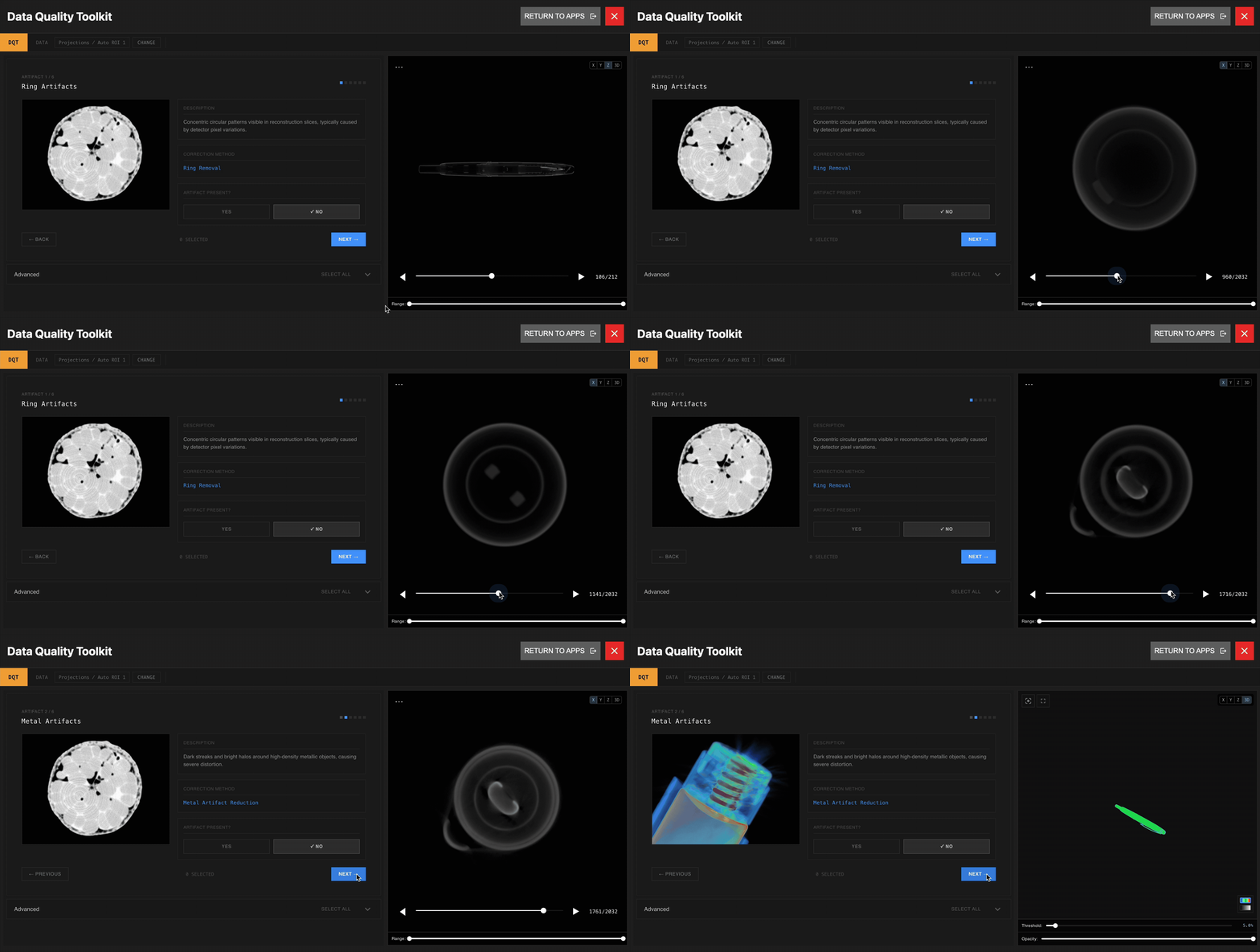 At the end of the artifact modules, the Configuration Summary displays the corrections queued based on which artifacts were selected.
Some corrections have parameters that must be specified. On the next page, choose any necessary parameters for the queued corrections. For each correction, a description explains how parameters should be chosen.
At the end of the artifact modules, the Configuration Summary displays the corrections queued based on which artifacts were selected.
Some corrections have parameters that must be specified. On the next page, choose any necessary parameters for the queued corrections. For each correction, a description explains how parameters should be chosen.
Manually choose corrections to apply at this step within the Advanced Tab of the Configuration Summary. Beam Hardening Correction and Downsampling correction techniques are available within the Advanced Tab.
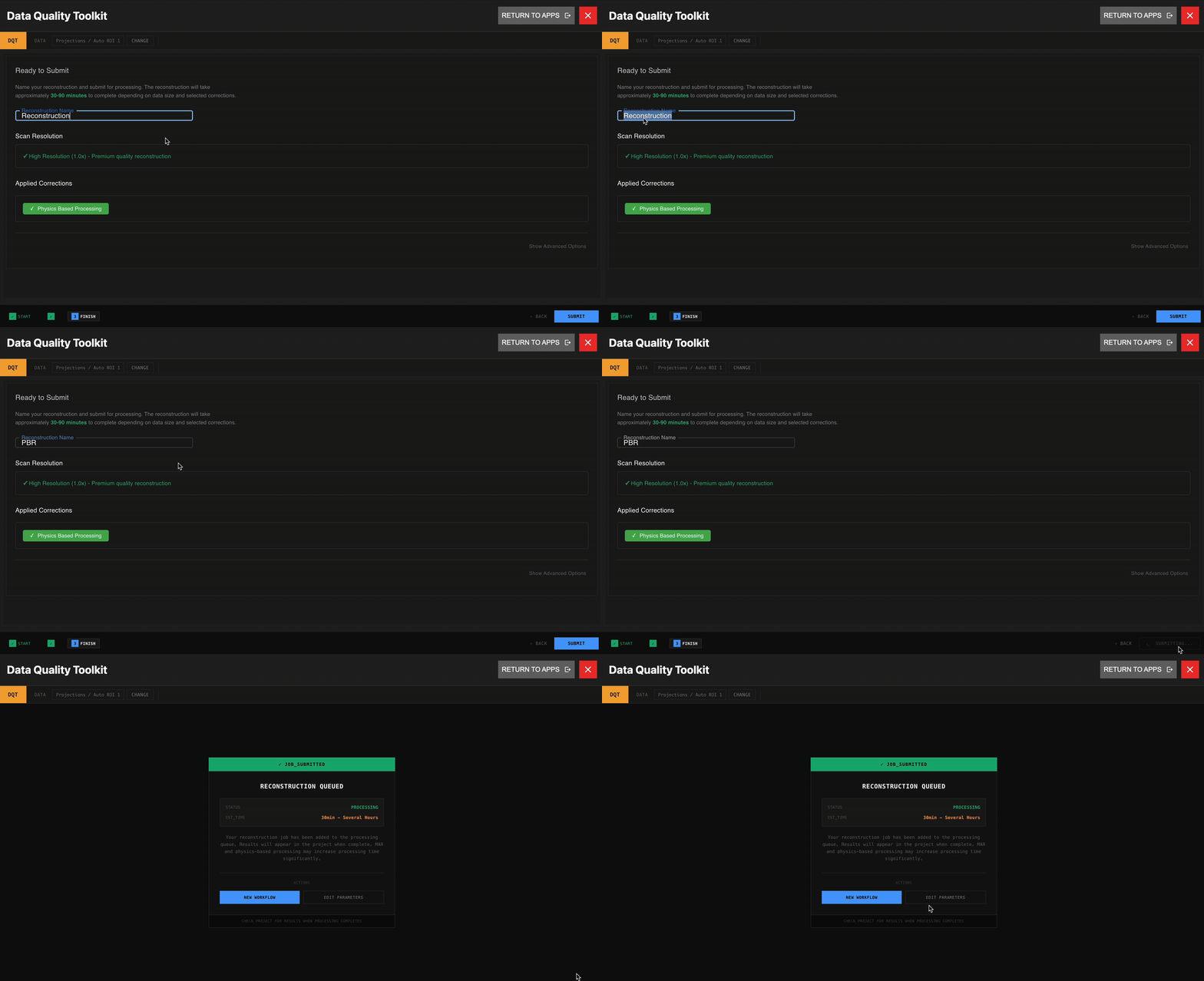
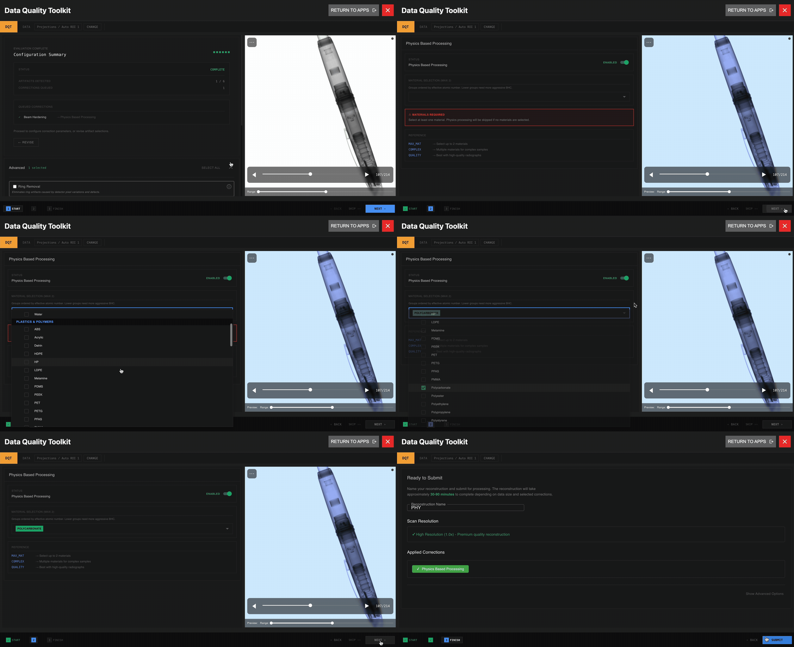 Submit the Workflow. The estimated time until the Workflow completes will be displayed, and the new Reconstruction will automatically populate in the Data Panel when ready.
Artifact removal techniques
Learn more about each of the artifact removal techniques in the Data Quality Workflow below to understand how it improves scan data.Metal Artifact Reduction (MAR) and Cone Beam Reduction are only available for Standard Reconstructions.
Ring Removal
Ring Removal
Eliminate artificial ring patterns that can be confused with real defects. When no physical ring was present in the part but rings appear in the scan data, use Ring Removal to remove these unwanted circular artifacts.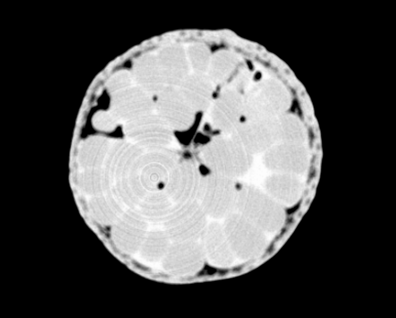
Metal Artifact Reduction (MAR)
Metal Artifact Reduction (MAR)
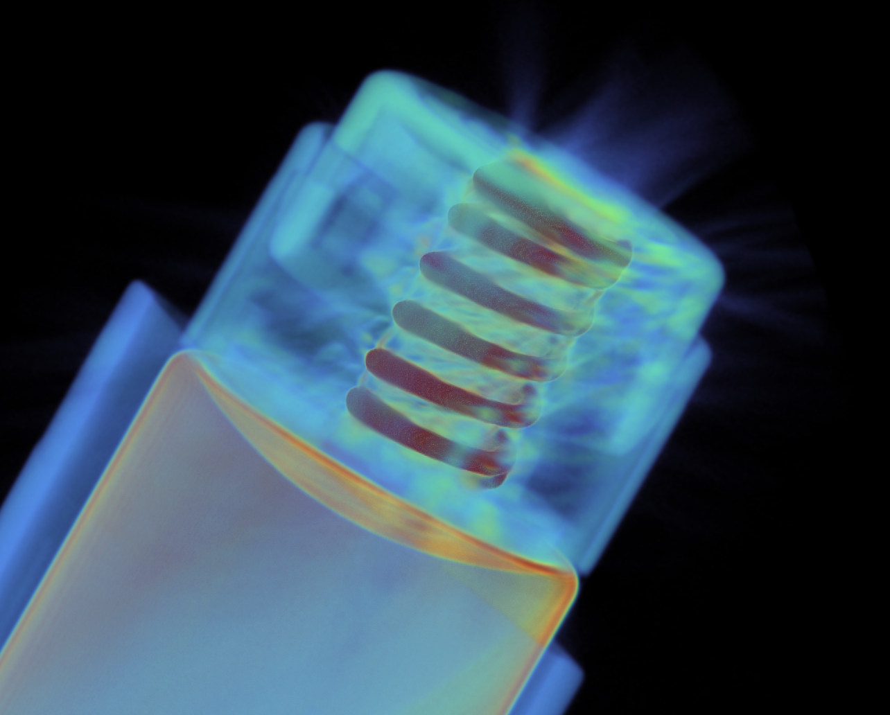
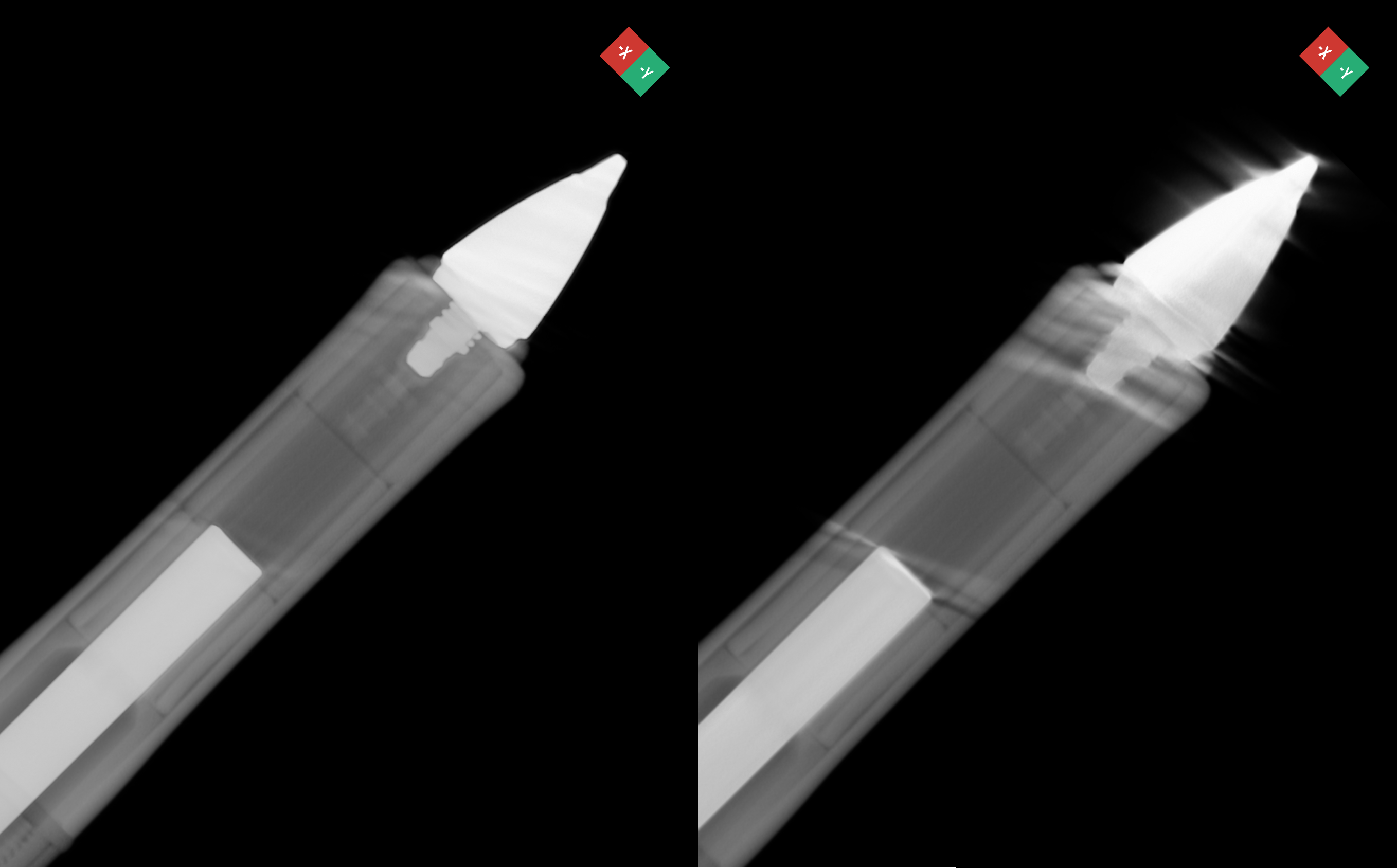
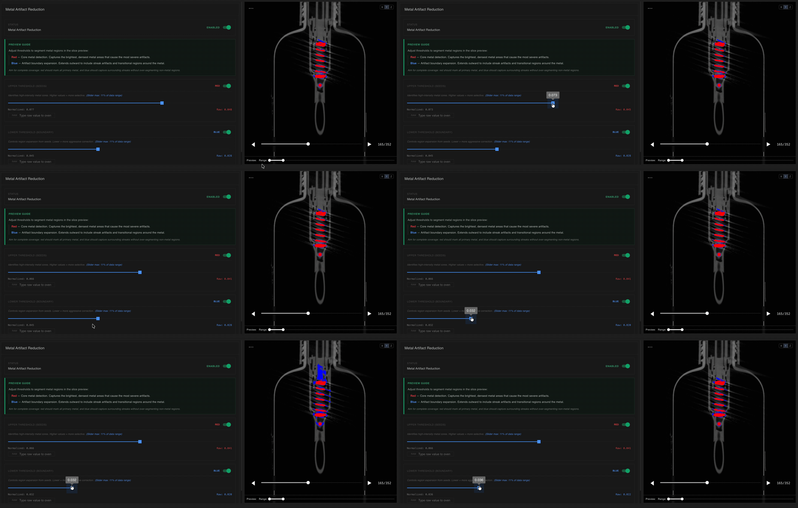
- Identify the metal regions and metal artifacts in your part.
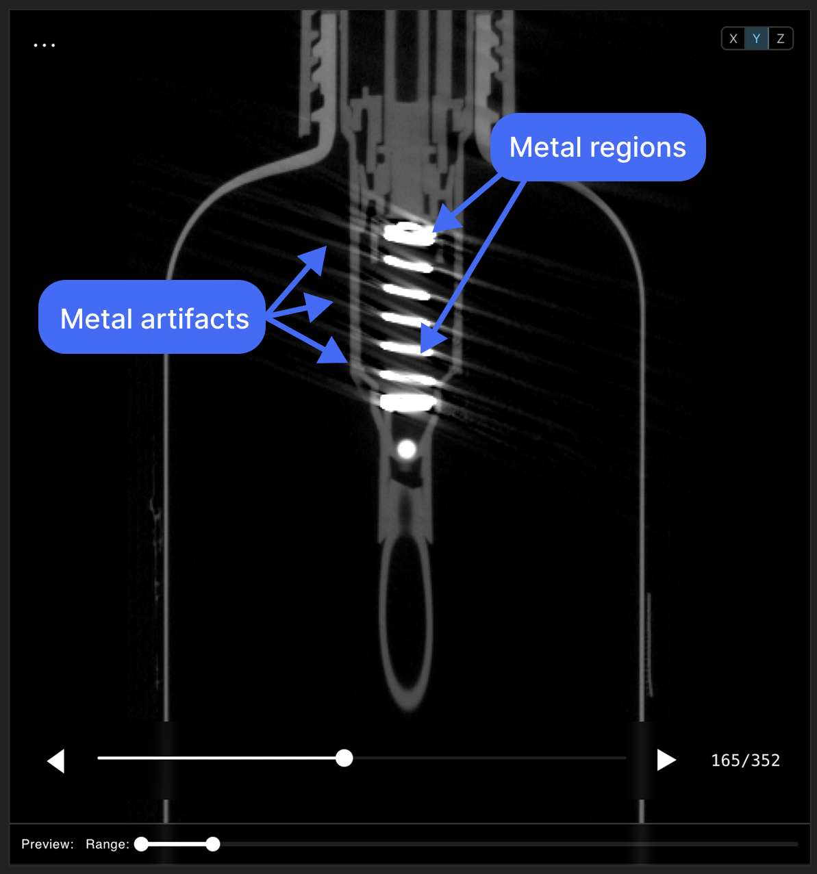
- Adjust the threshold sliders such that metal regions are highlighted in red, and surrounding/artifact regions are highlighted in blue.
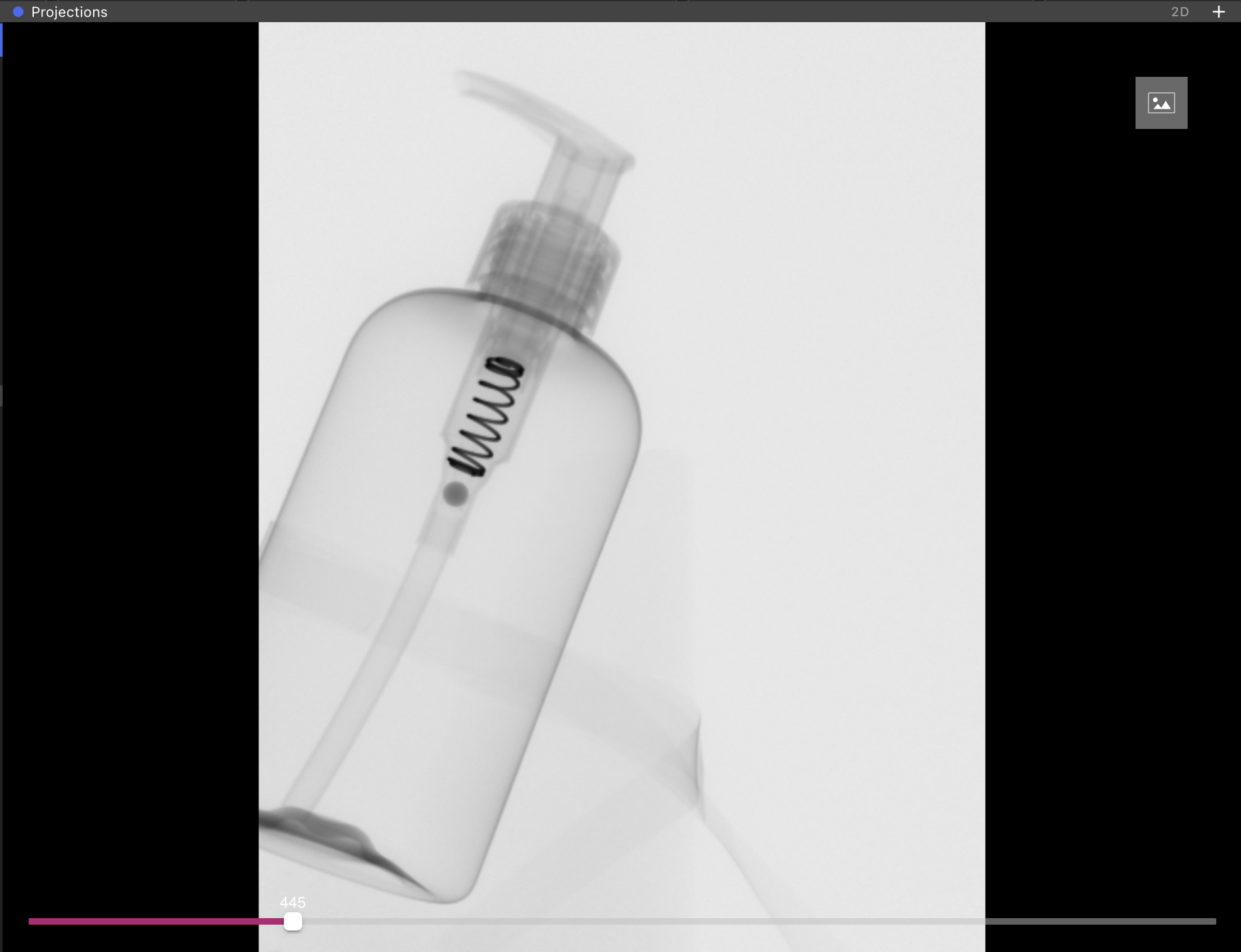
- Soap dispenser pumps
- Screws in plastic assemblies
- Electronics
- Needles in injection-molded housings
- When metal completely or substantially surrounds the regions with artifacts. MAR corrects artifacts in regions around small metal components, not when metal comprises a large portion of the part.
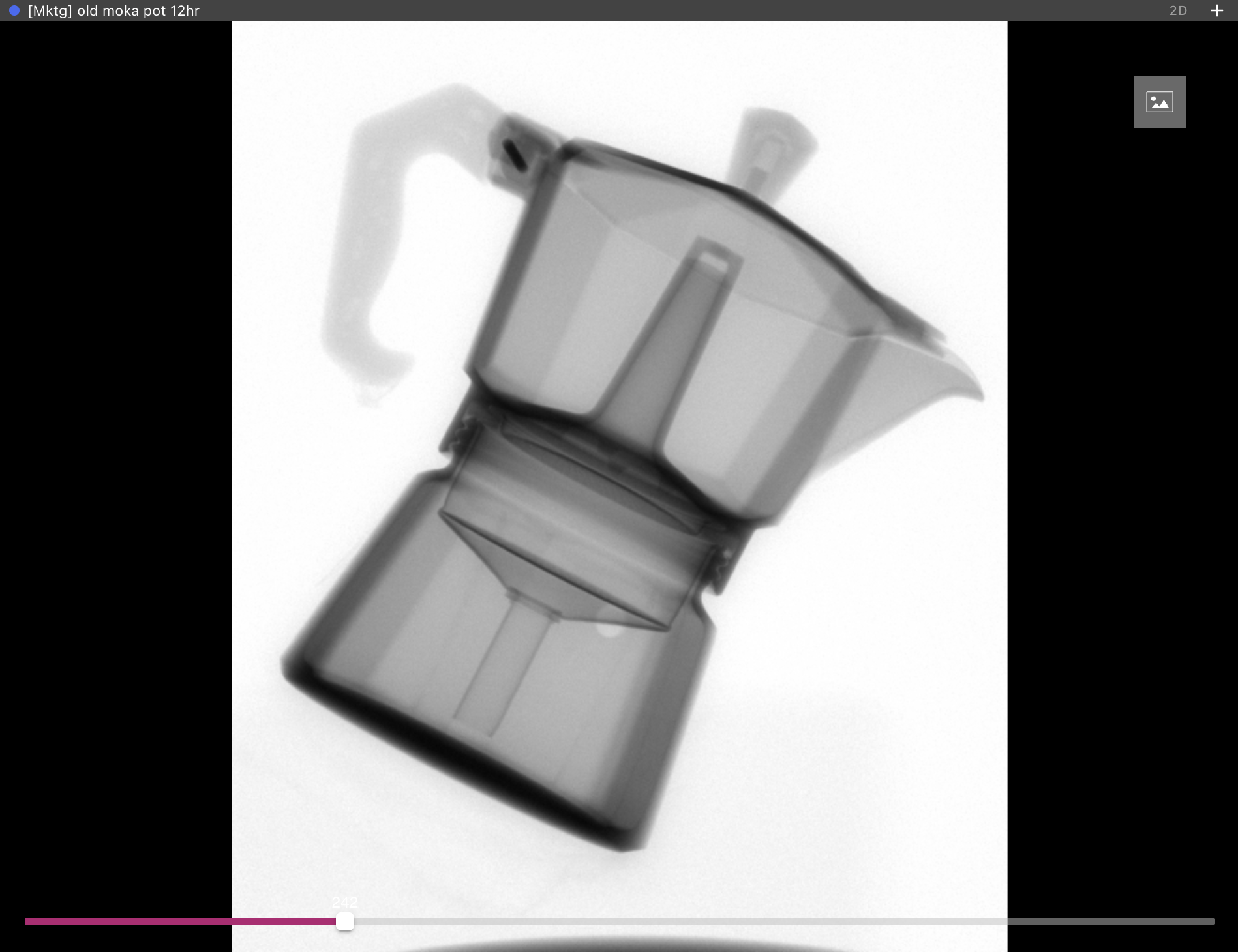
- When any component of the part leaves the scan volume, as in a offset or region-focused scan.
Physics-Based Processing
Physics-Based Processing
Applies material-aware, physics-based corrections to reduce Beam Hardening artifacts—like cupping and streaking—in reconstructed images. Physics-Based Processing models complex interactions (X-rays, scatter, and material attenuation) to restore accurate contrast and geometry, and works alongside other artifact-reduction techniques to deliver more accurate, higher-quality scans.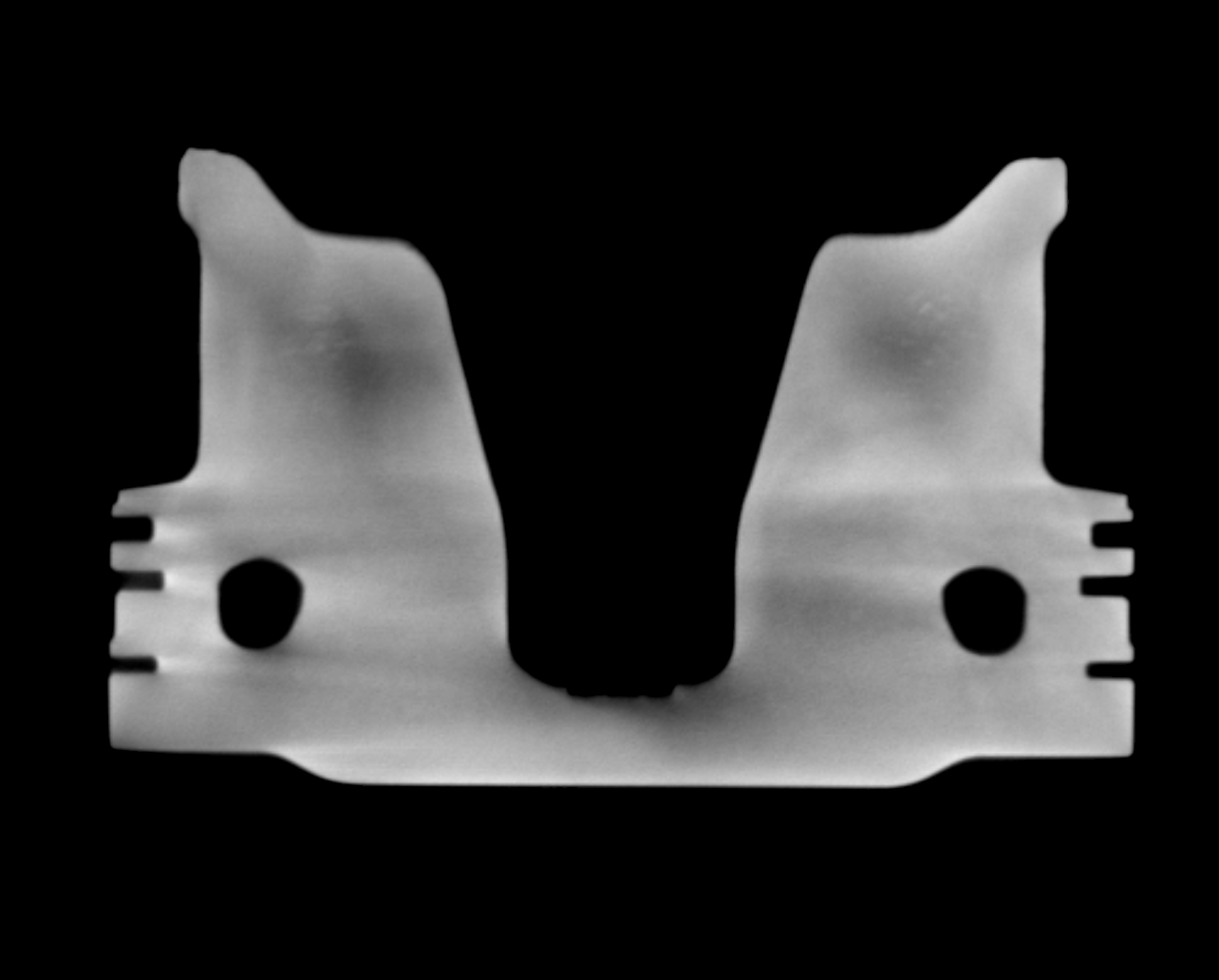 Choosing materials: select up to four materials present in the scanned part. Selecting the exact materials will result in a Reconstruction with the best results, but doing so is not always possible: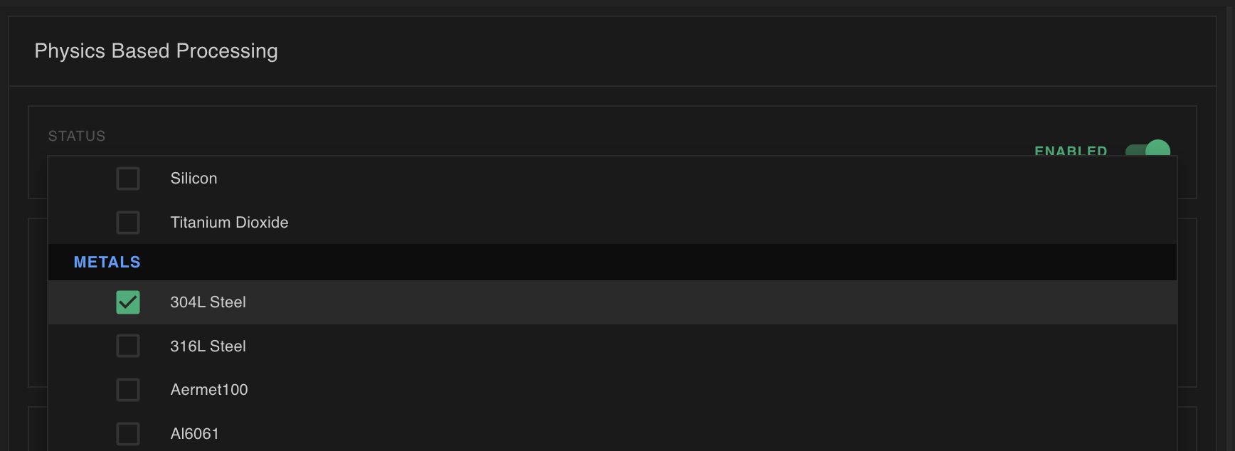
- If the materials present are not included in the list to select from, choose an approximation that has a similar density and atomic number to the materials presents.
- If you’re not sure what materials are present, choose four materials:
- Choose at least your best guess of the lowest- and highest-density material in the part
- Choose up to two more materials likely to be present in the part. For example, if scanning an electronic component, you may choose ABS (lowest density), copper (highest density), eglass and stainless steel (common electronic components).
Axis of Rotation (AOR) Correction
Axis of Rotation (AOR) Correction
Fix small misalignments in the scanner’s rotation center that cause doubling, blurring, or asymmetry in reconstructions. If features appear duplicated or smeared because the rotation axis was off, apply AOR Correction to realign the projection geometry before reconstructing the volume.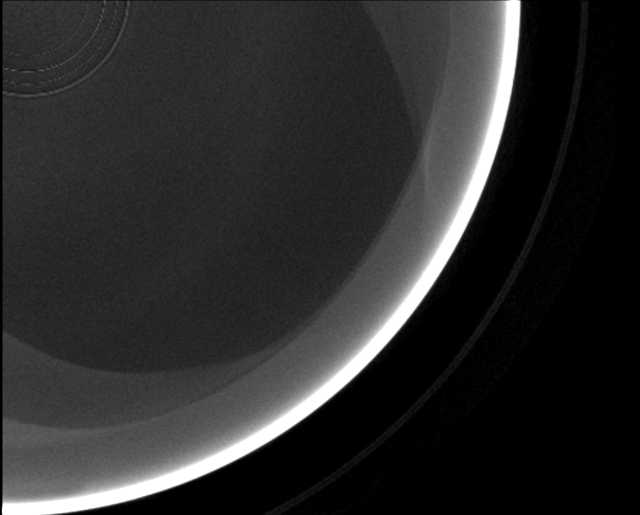
Denoising
Denoising
Reduce random noise in radiographs or reconstructed volumes while preserving genuine features. When scans are grainy—for example from short exposure time and high gain—use Denoising to suppress noise so defects become easier to detect without erasing real structures.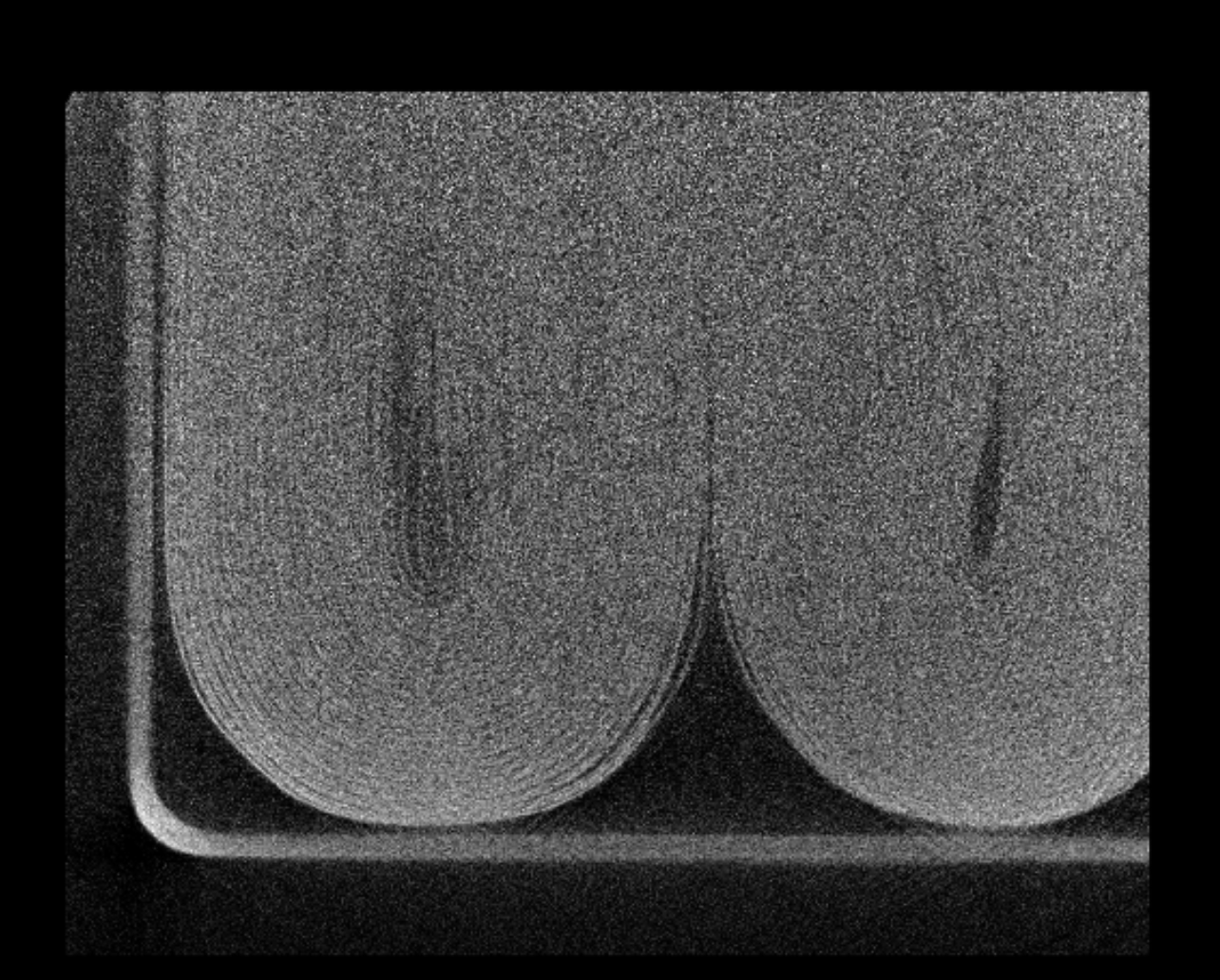
Cone Beam Reduction
Cone Beam Reduction
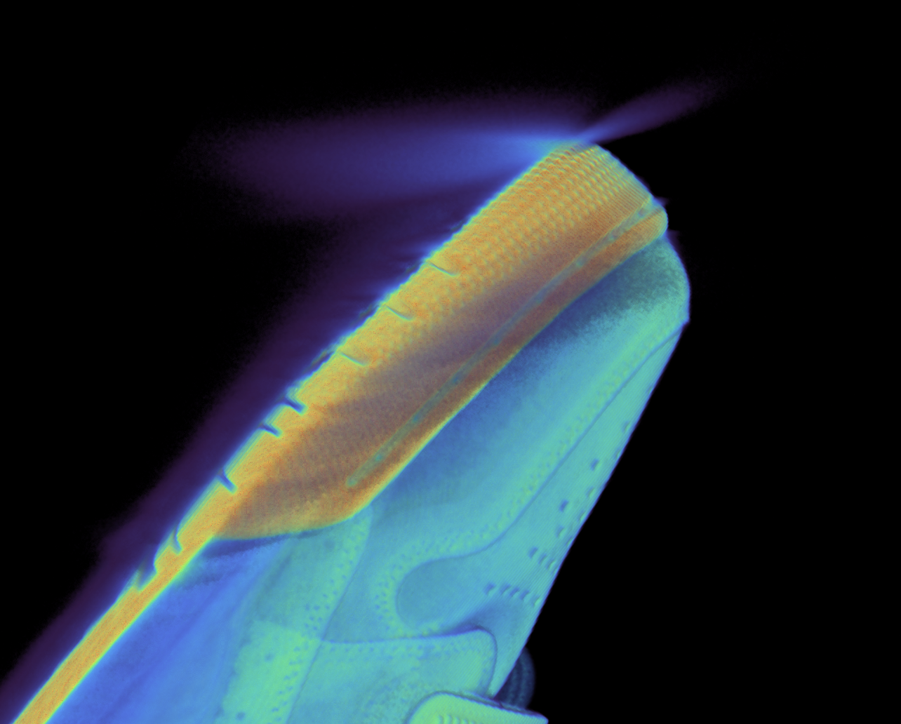
Reduces streaking and shading that appear at object tips and edges near the top and bottom of the scan volume. These artifacts form on surfaces parallel to the principal ray along the rotation axis (and are worsened by wide cone angles); Cone Beam Reduction corrects the cone-beam geometry to restore accurate edge/tip shape and contrast.