Uses of a Mesh
- Meshes can enable dimensioning of planes with higher precision than using raw volumetric data - see ISO-50 Mesh Generation and Dimension Point Snapping.
- Compare two Meshes with the Compare Tool, as between two parts of the same SKU or between an ideal CAD file and a part’s Mesh.
- Export a Mesh as an .STL file for use in external tools, as in the Reverse Engineering Workflow
Creating a Mesh
Begin by selecting the Reconstruction or ROI that will serve as the source of the Mesh. Select the Mesh Tool from the Toolbar to open the Mesh Workflow Editor.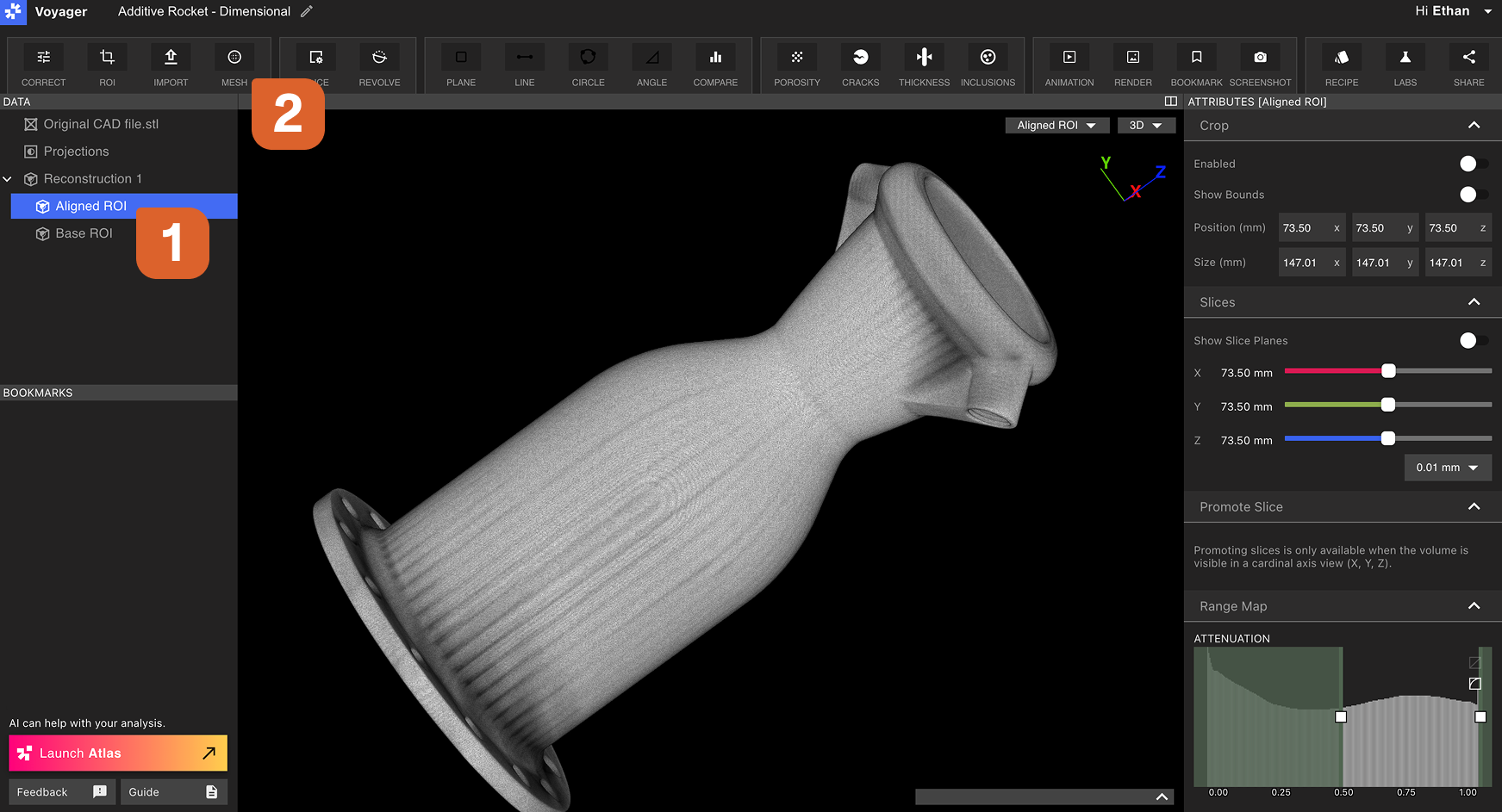
Volume
Modify which Data Object in the Project will serve as the source of the Mesh. When changed, the new Data Object will replace the old one in the Viewport.Use ISO-50 threshold
This toggle can be enabled when generating a Mesh of a mono-material part. ISO-50 is an automatic threshold selection method - the Mesh Threshold selector will disable when ISO-50 Mesh Generation is enabled. ISO-50 produces a dimensionally accurate boundary for single material scans (like polymers and lighter metals). Read more within ISO 50 Mesh Generation and Dimension Point Snapping.Isolate largest body and remove residual material
When enabled, the Mesh will include only the largest connected body in the source Data Object. If other smaller components are present, they will be excluded from the Mesh.Isolate largest body and remove residual material can also remove porosity and noise from a Mesh, as they often appear as small regions of polygons disconnected from the surface of the largest body.
Mesh thresholds
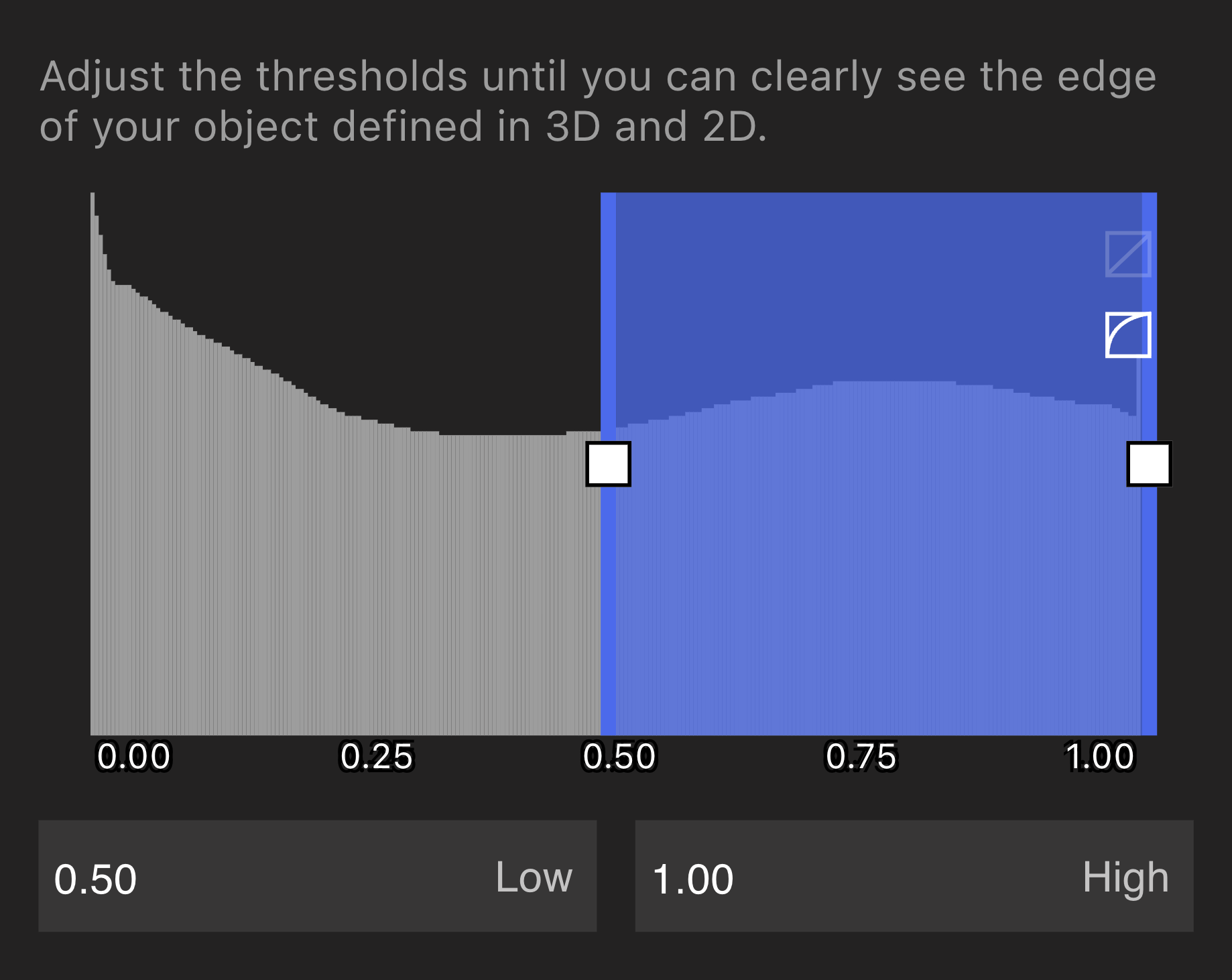
Iterate on the threshold by generating multiple Meshes in series to understand what different threshold values produce.
Isolate Peaks in Data Histogram
Isolate Peaks in Data Histogram
Our Mesh generation Tools have the ability to isolate specific materials in multi-material scans. For instance, in this example, this Luer Lock is built of components made from multiple different polymers. You can see the clear distinction between the materials as peaks in the data histogram.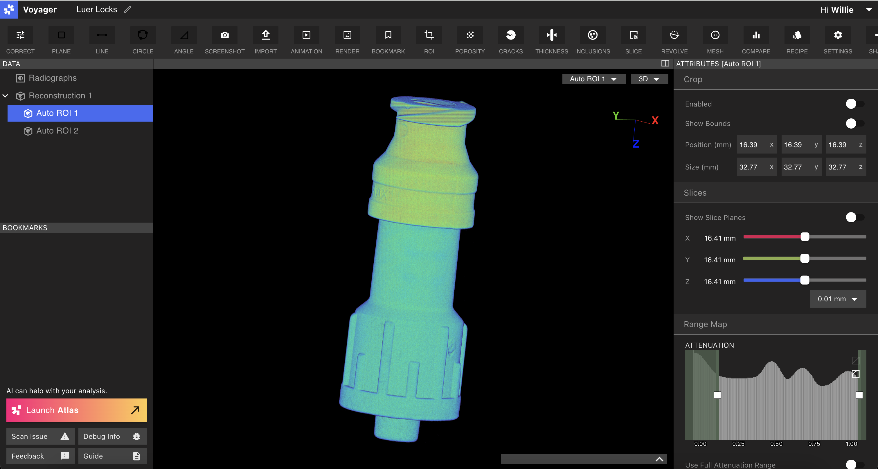
Mesh Material 1
Mesh Material 1
When entering the Mesh Workflow, you’ll see that the rangemapper has inverted, and instead of excluding material, the barn doors now allow you to select which material to include. 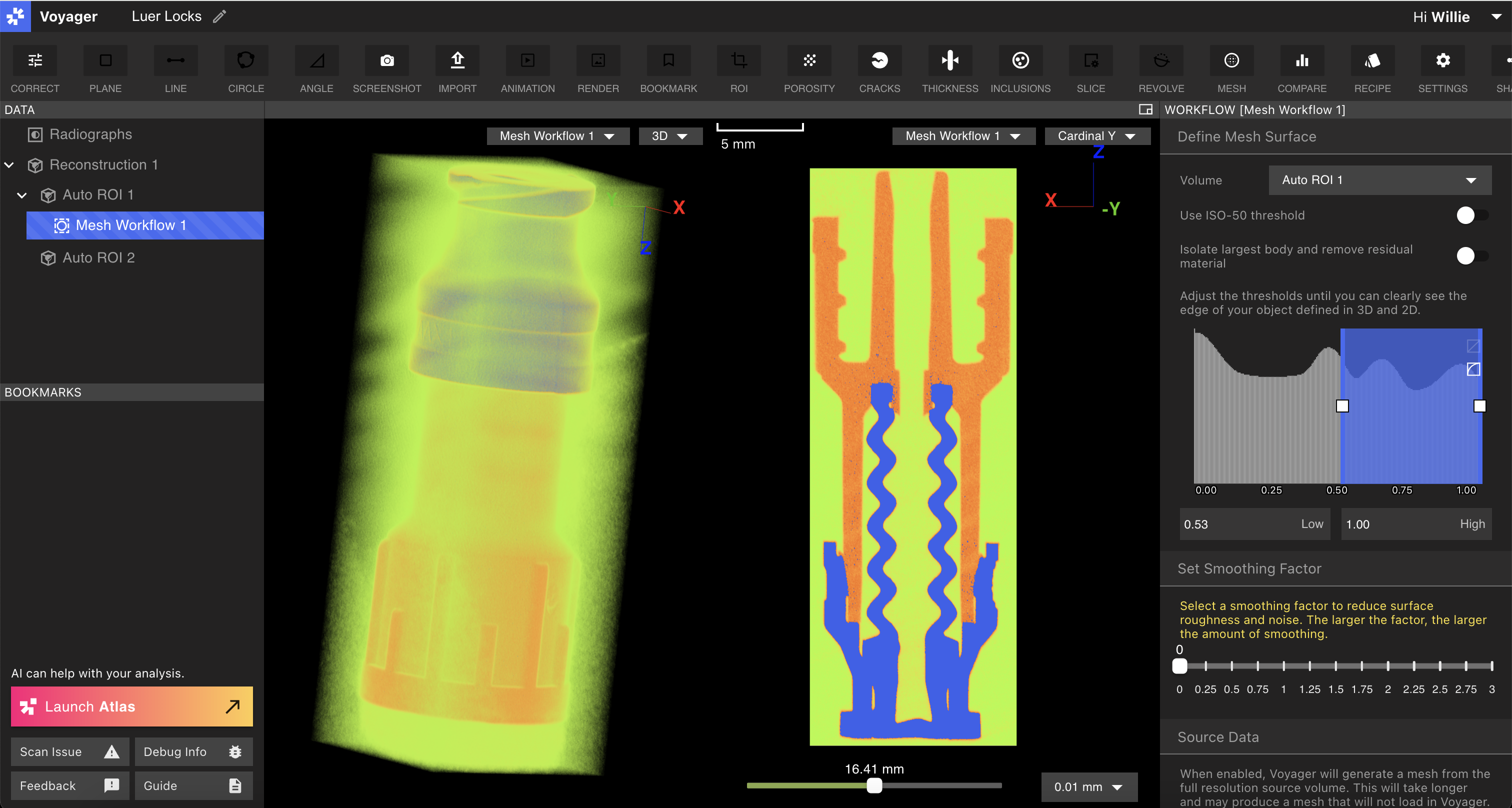
Mesh Material 2
Mesh Material 2
The boundary between each material peak is near the valley of any two peaks. Depending upon your goals, you can eyeball this, or you can pursue more robust calibration workflows to establish a foundation for dimensional work. Evaluate the boundary for the second material in the same way, and submit that Mesh request to Voyager. 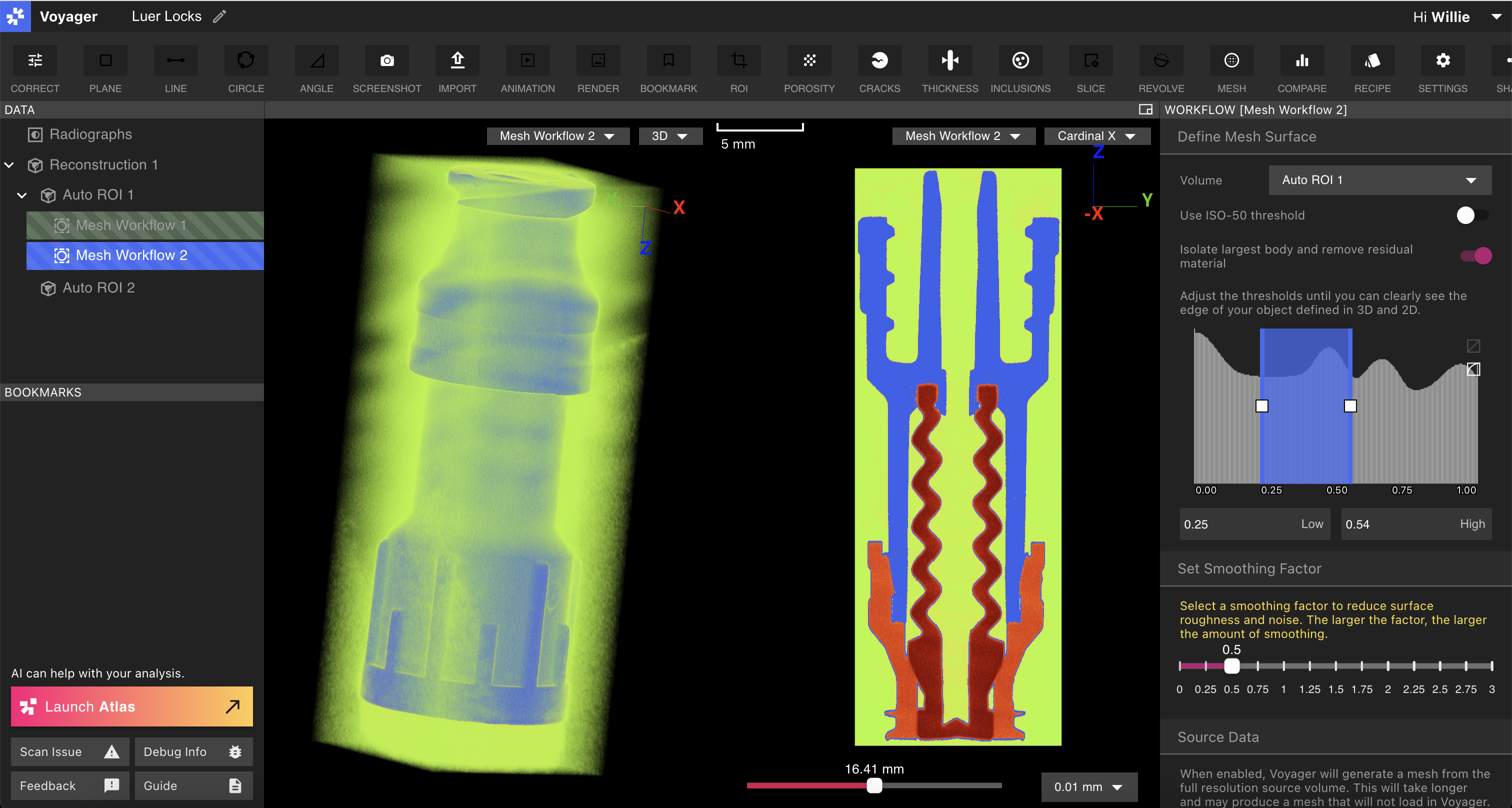
Results
Results
The resulting Meshes will be separate Meshes per material type that you selected during the Mesh workflow. 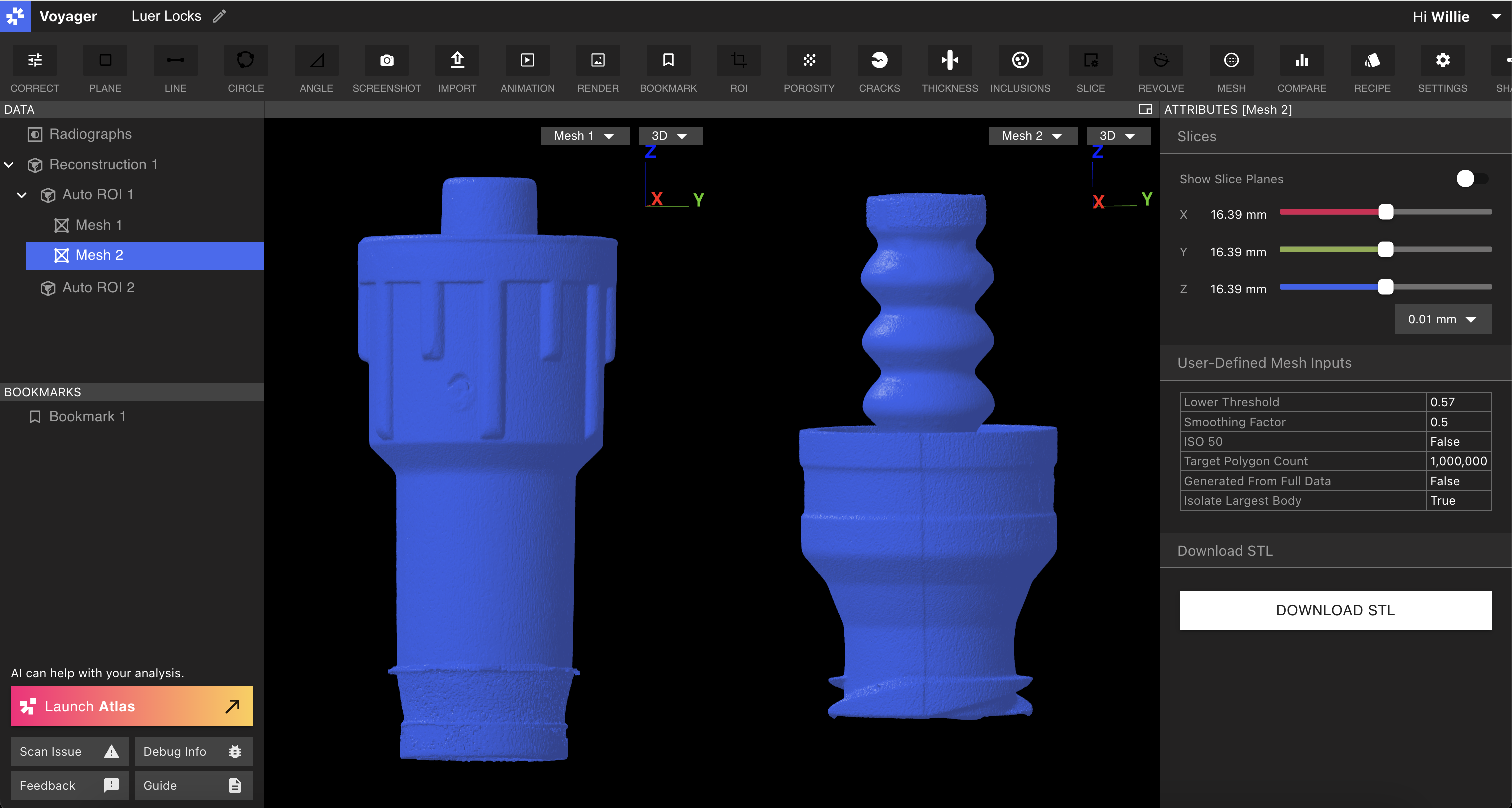
Note on threshold accuracy:Accurate Meshes are a result of accurate thresholds. In order to establish an accurate threshold, calibrate our system by scanning a part of the same material with known dimensions and iterating on the threshold required to achieve the correct dimension.
Smoothing Factor
Creating a Mesh from volumetric data involves segmenting the volumetric data into two or more groups to define which parts of the volume correspond to discrete materials. Voyager currently supports a binary segmentation. When the segmentation is performed, artifacts or noise in the scan can make the boundary between the values slightly inaccurate. This often appears as high frequency, low amplitude noise on the surface of the resulting Mesh. Mesh smoothing can resolve this high-frequency surface noise and result in a Mesh that is more accurate to the real object. It is worth noting that Mesh smoothing can reduce accuracy in some specific areas, such as creases or corners. On balance, however, Mesh smoothing offers the opportunity to smooth the surface of a Mesh and can be used judiciously to get better meshing results.