

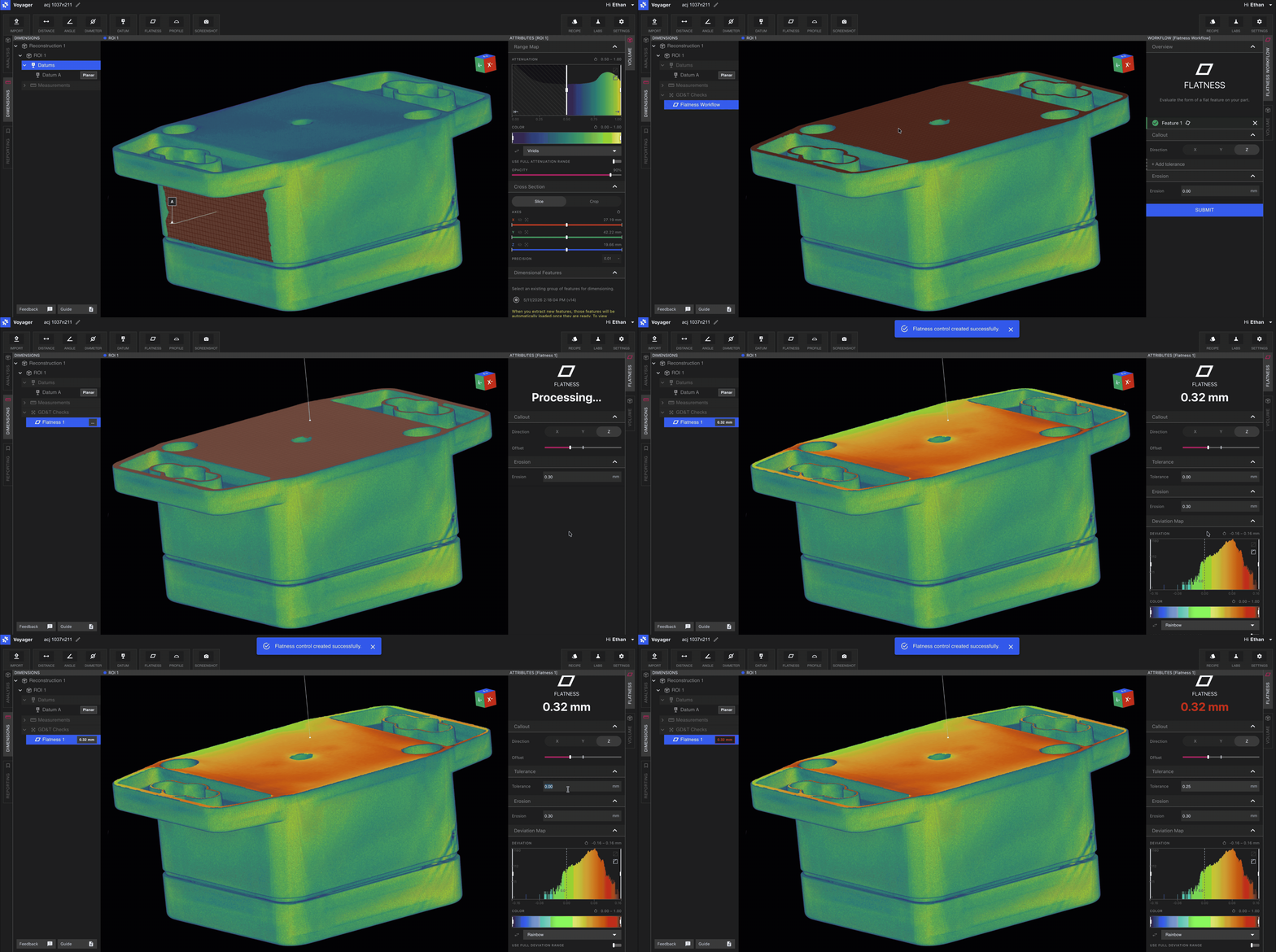
What the number means
The reported flatness is the width of the zone that contains the evaluated surface. A smaller number is a flatter face. The Viewport draws that deviation as a heatmap on the plane, and the callout carries the value and a pass or fail state against the tolerance you entered. Erosion drops surface points within a distance of the selection’s edge. Edge points from extraction are often noisier than the body of the face. A small erosion keeps the evaluation on the face you care about. It does not change the plane feature itself.Workflow
1
Select Flatness
Choose Flatness from the Toolbar in Dimensioning Mode, or right-click a plane and choose Add flatness control….
2
Choose a plane
Click the plane. Eligible planes highlight on hover.
3
Set erosion and tolerance
Enter an erosion distance, in millimeters, and a tolerance. Erosion can stay at zero.
4
Submit
Submit to add the control to the feature set. The heatmap and the callout appear on the plane.