Supported datum types
Voyager currently supports three datum types:- Plane — built from a single extracted plane feature
- Axis — built from a single extracted cylinder feature
- Midplane — built from a pair of parallel plane features
Defining datums on a scanned part
1
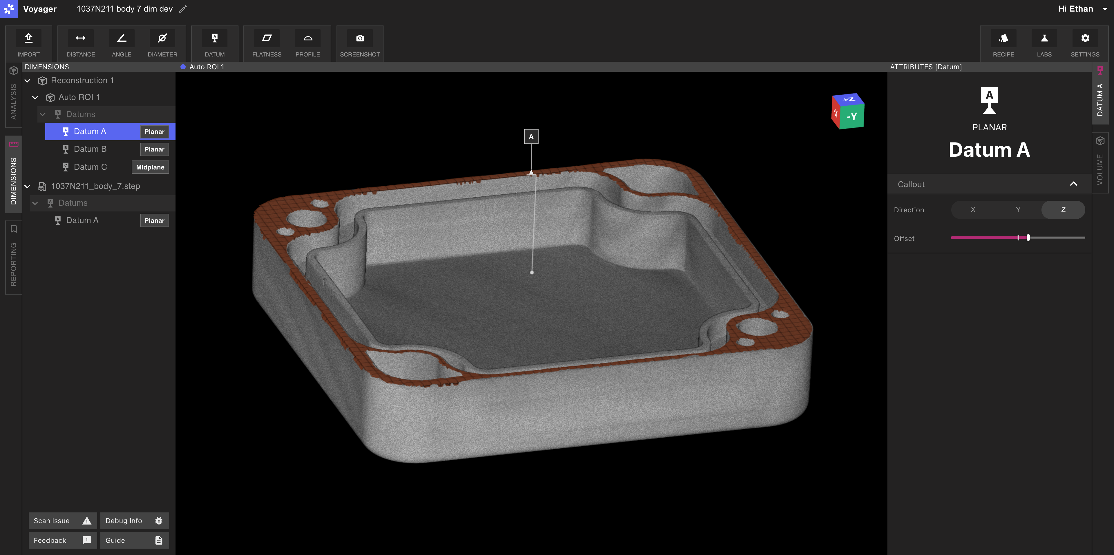
Select the Datum Tool
Choose Datum from the Toolbar in Dimensioning Mode.
2
Choose a datum type
Pick Plane, Axis, or Midplane.
3
Pick the source feature(s)
Click the extracted plane (Plane), cylinder (Axis), or pair of parallel planes (Midplane). Eligible features highlight on hover.
4
Label and submit
Assign a label (such as
A, B, or C) and submit. The new datum is added to the scene.Defining datums on imported CAD
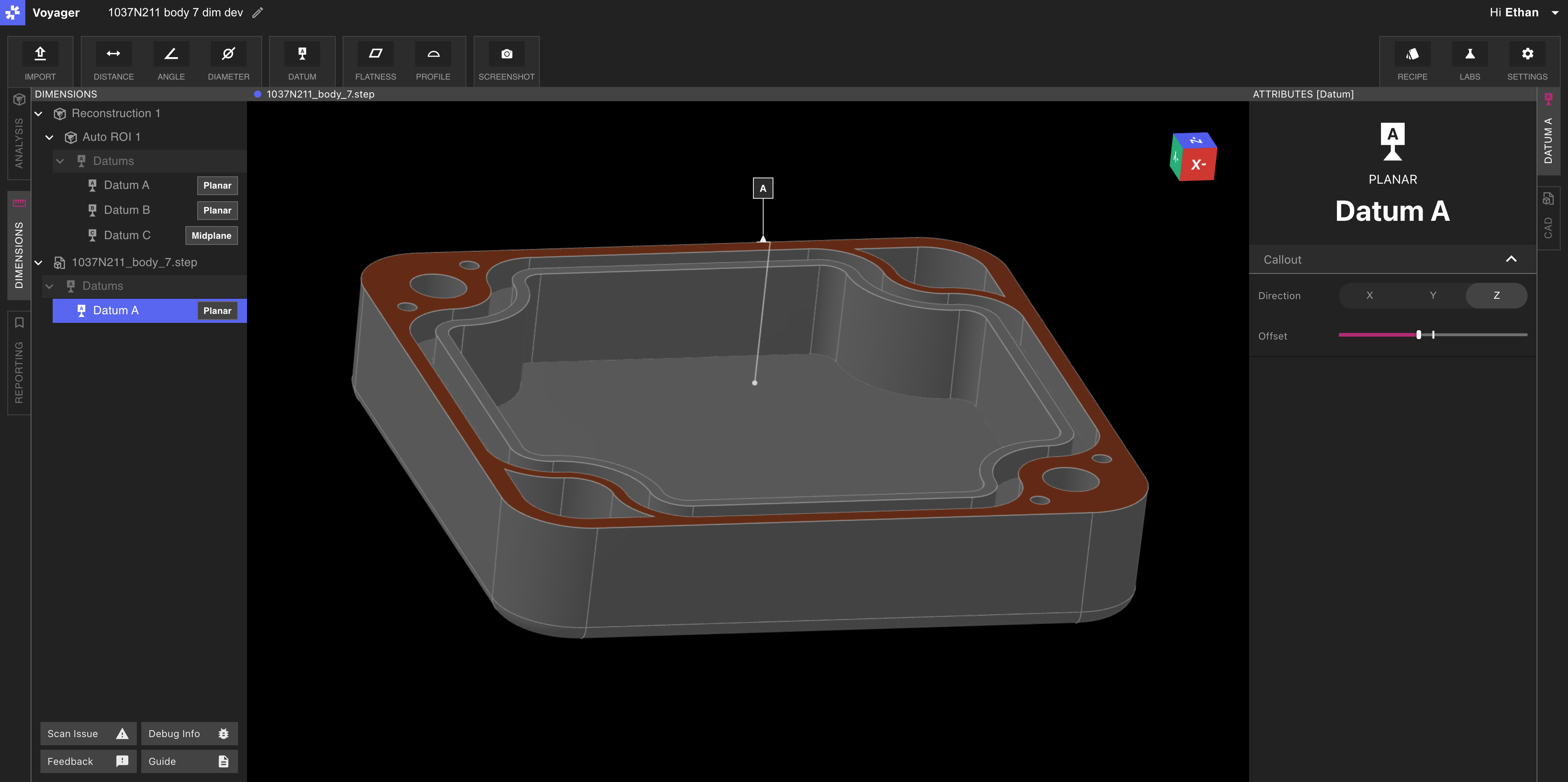
.STEP file into your Project — see Nominal CAD Import for the focused walkthrough — then run the same Datum workflow against the CAD body.
For Profile, you must define a corresponding DRF on both the imported CAD and on the scanned part. Matching labels (for example,
A, B, C) on each side enable Voyager to correlate the two frames in the Profile workflow’s datum-correlation step.Adjusting leaders and labels
Each datum displays a leader and a labeled flag in the Viewport. Use the leader and label controls in the Attributes Panel to adjust orientation and offset. Clean placement makes it easier to read complex DRF setups in Reporting Mode Bookmarks, Renders, and Animations.Related pages
- 3D Auto-Dimensioning
- Direct Dimensions
- Flatness
- Profile — uses datums to align CAD and part for evaluation
- Nominal CAD Import — focused STEP-import walkthrough
- Import Tool — main Mesh and CAD import article
- Voyager Modes
- Voyager 2.0 Release Notes and Monthly Highlights