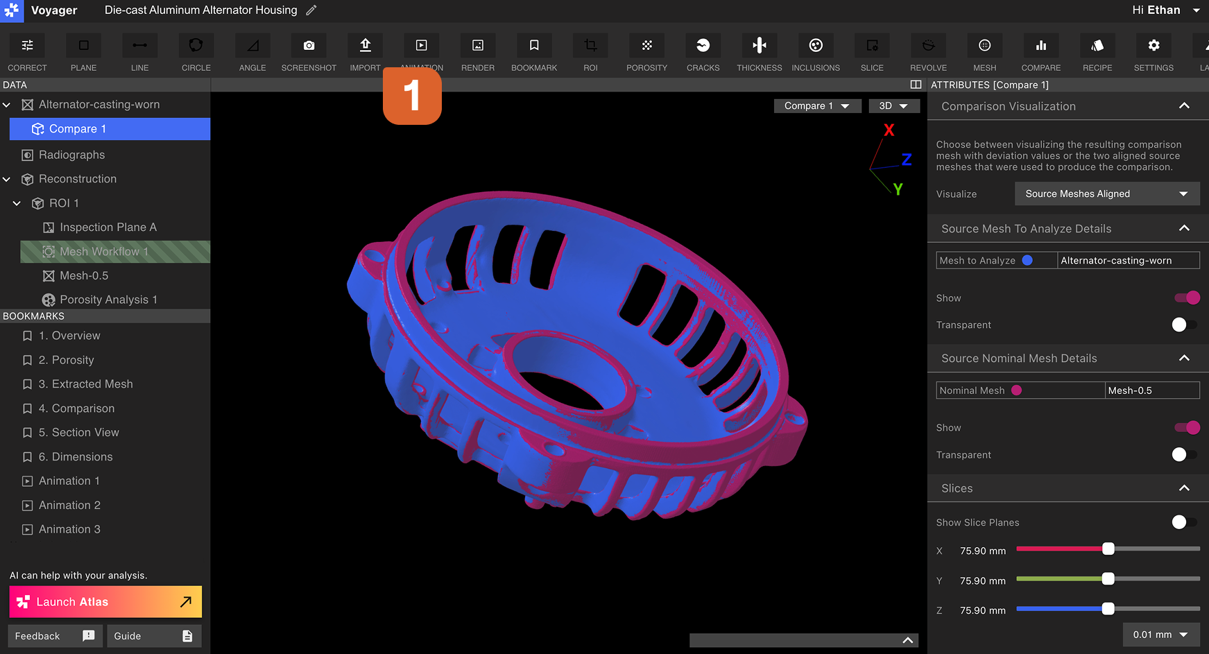
Importing an STL Mesh (Analysis Mode)
From the Toolbar in Analysis Mode, select the Import Tool, choose a file to upload, and set the Mesh scale matching the unit set in your.STL file.
A common default for
.STL files from external software is mm, which is also the default for .STL files exported from Voyager.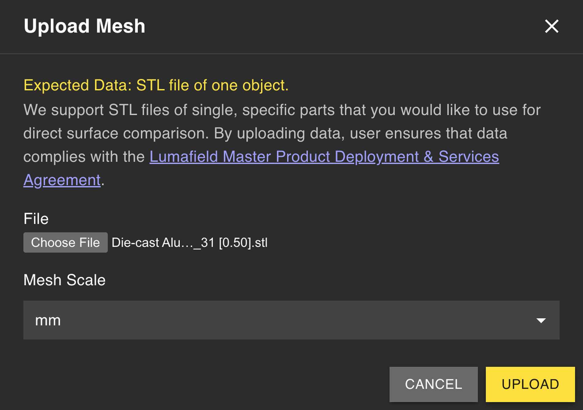
Importing a STEP CAD file (Dimensioning Mode)
From the Toolbar in Dimensioning Mode, select the Import Tool to upload a.STEP file as the nominal CAD body for your scanned part. STEP imports are the foundation of the Profile workflow, which compares your scan against the nominal CAD under a Datum Reference Frame.
1
Open the Import Tool in Dimensioning Mode
Switch to Dimensioning Mode and select the Import Tool from the Toolbar.
2
Upload your .STEP file
Choose the STEP file representing the nominal part. STEP carries native units and exact geometry, so no scale entry is required.
3
Define datums on the imported CAD
Use the Datum Tool to build a Datum Reference Frame on the imported CAD, mirroring the DRF on the scanned part. Matching labels (for example,
A, B, C) make datum correlation in the Profile workflow trivial.4
Run Profile
With matching DRFs on the part and CAD, run Profile to compare the scan against the nominal CAD.
Related pages
- Voyager Modes
- Compare Tool — STL-based Mesh comparison in Analysis Mode
- 3D Auto-Dimensioning
- Datum Definition
- Profile