Introduction
Lumafield’s Neptune scanners offer an accessible workflow for office, factory, or lab settings. Using the touchscreen interface and included fixturing kit, anyone can quickly prepare and configure parts for inspection. Follow the steps below to run a scan on your Neptune.Scanner start-up
Before you begin, ensure the scanner is properly homed and warmed. If these steps have not been completed, refer to the Neptune Machine Initialization guide. Confirm that green check marks are visible in the bottom left corner of the interface, indicating the system is ready for operation.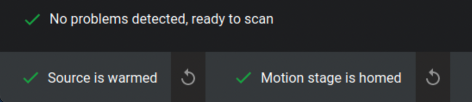
Four steps to running a scan
1
Fixture the part
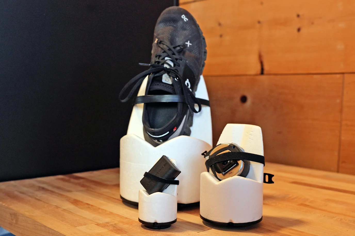
- Weight Limit: The rotary stage supports a maximum sample weight of 5 kg (11 lbs).
- Density: Use low-density fixturing materials (like foam) to make it easier to isolate your part during analysis.
- Orientation: Angle flat surfaces to reduce scan artifacts and improve image quality.
- Stability: Ensure the part is completely stationary to prevent motion-related errors.
- Customization: Use the ¼-20 threaded baseplates to design custom buildplates tailored to your part geometry.
2
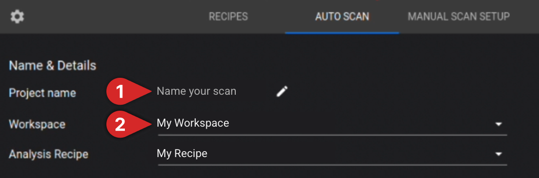
Name the scan and select its destination
3
Position the part
With the scanner door open, secure your fixture to the rotary stage and gradually increase the magnification. Periodically perform a full 360° rotation to verify that the part and fixturing maintain adequate clearance from the X-ray source, filter wheel, and detector.Neptune Microfocus demonstration

4
Configure scan settings
The following Auto Scan settings must be selected to begin a scan: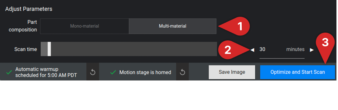
- Select Material Type: Specify whether your part is “Mono-material” or “Multi-material”
- Set Scan Time: Adjust the scan duration using the slider or by manually entering the desired time
Note: Increasing the scan time generally improves scan quality.